
Since starting this program, it has been made abundantly obvious that if you are extroverted in public situations such as the almost daily “share-out” sessions we have, you are going to get more feedback and your ideas will be remembered more vividly. In order to solve this problem, I created Queue, the physical/digital meeting facilitator that takes the form of the cursive capital letter “Q”.
Materials:
- SLA clear resin
- Solderless breadboard
- 1 led integrated intermittent push button
- 1 led integrated toggle push button
- braided strand wire
- 4 neopixel RGBW quarter rings, each with 15 neopixels
- sand paper
Initial Sketches:


The Process: 3D rendering and printing the “Q”


This was my first 3d render ever and I definitely have a lot to learn. The mesh’s were not quite aligned in a few places, leading to a few holes and tears in the final model.
Printed Model:


Finishing:
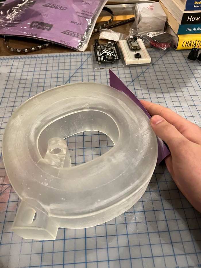
I did some finish sanding in order to increase opacity and diffusion of LED’s.
Code:
My original idea for the code was for it to allow the object to judge time and limit each speaker to a certain amount. As well, it would record in an external google sheet utilizing IFTTT. In the essence of have a presentable prototype, I instead chose to program a “simple” button cycler code where a section of 10 pixels at a time would light up in a separate color, denoting a different person to speak next.
#include <Adafruit_NeoPixel.h> // include the Neopixel Library in this Sketch
#include <Adafruit_NeoPixel.h>
#ifdef __AVR__
 #include <avr/power.h> // Required for 16 MHz Adafruit Trinket
#endif
 #define BUTTON_PIN   2
#define PIN 13 // This is the Arduino Pin controlling the LEDstrip.

#define NUMPIXELS 60 // Here, you are informing how many LEDs you have on your strip.
                     // You can also control only a part of the existing LEDs, if you wish.
                     // This strip has 60 LEDs, so I am informing this number.

/*
 *  Remember that I keep annoying you whith capi tal IMPORTANT warnings? This next line is where it really matters.
 */

Adafruit_NeoPixel pixels = Adafruit_NeoPixel (NUMPIXELS, PIN, NEO_RGBW + NEO_KHZ800); // Here, you are specifying your strip,
                                                                                     // Let's go over the details:

/*
 * The command Adafruit_NeoPixel pixels assigns (inside the parenthesis, separated by commas (,)):
 * 1) the number of pixels you control, We have created the variable NUMPIXELS, so we can change this number more easily according to our need
 * 2) the PIN on the Arduino Board that sends the signal. In this case, we use PIN 06, as declared globally above
 * 3) The Type of LED flag. In this case, we have a RGB White LED, with 800Khz bitstream. You can check this out on the datasheet we linked above.
 *
 * Please notice that your LEDs won't work if you do not get this line right. So, here are some tips for more recent fixtures:
 *
 * NEO_KHZ800 will be common in most NeoPixel products with WS2812 LEDs. If you check the datasheet, of your strip, it should be under
 * data speed, or something similar.
 * NEO_KHZ400 will be preent in WS2811 LEDs. Again, check the datasheet to be sure.
 *
 * NEO_GRB will be common in NeoPixel products
 * NEO_RGB will be common in Flora Pixel products.
 *
 * REMEMBER, if yor LED is a RGB White, you have to add a W at the end of this code, so they will be either NEO_RGBW or NEO_GRBW
 */

/*
 * OK, now let's start controlling the leds. The strip I am using has 60 LEDs. I want to control it in 6 groups of 10 LEDs, to make my life easier.
 * So, let's define the following arrays:
 */
boolean oldState = HIGH;
int     mode     = 0;
int PXL1[] = {0,1,2,3,4,5,6,7,8,9}; // array controlling the first 10 LEDs. Please notice the "LED 0" is the first one, not "LED 1"
int PXL2[] = {10,11,12,13,14,15,16,17,18,19};
int PXL3[] = {20,21,22,23,24,25,26,27,28,29};
int PXL4[] = {30,31,32,33,34,35,36,37,38,39};
int PXL5[] = {40,41,42,43,44,45,46,47,48,49};
int PXL6[] = {50,51,52,53,54,55,56,57,58,59};

int delayval = 50; // Here we set a delaytime
int delayExtra = 300;

void setup() {
  pinMode(BUTTON_PIN, INPUT_PULLUP);
  pixels.begin(); // Initialize NeoPixel strip object (REQUIRED)
  pixels.show();  // Initialize all pixels to 'off'
  pixels.begin(); // This initializes the NeoPixel library.

}

void loop() {

   boolean newState = digitalRead(BUTTON_PIN);

  // Check if state changed from high to low (button press).
  if((newState == LOW) && (oldState == HIGH)){
    newState = digitalRead(BUTTON_PIN);
    if(newState == LOW) {      // Yes, still low
      if(++mode > 9)
        mode = 0; // Advance to next mode, wrap around after #8
      switch(mode) {           // Start the new animation...
        case 0:


  for(int i=0;i<10;i++){ // Since each array has 10 LEDs, we are going to turn them sequentially on using this index.

/*
 * Notice that the lines below are just setting up the color of each pixel. This is not yet the command to turn them on. The
 * pixels.setPixelColor command is a very easy way to define the color of each pixel. The syntax is:
 * pixels.setPixelColor(x, pixels.Color(R,G,B)), where:
 * x = the pixel you want to define a color for. In this example, we are using the arrays we created for the 6 control groups, hence the PXL1[i] input.
 * R,G,B = the values of red, green, and blue on a RGB scale.
 */

  pixels.setPixelColor(PXL1[i], pixels.Color(255,255,255)); // array number 1 is magenta
//pixels.setPixelColor(PXL2[i], pixels.Color(255,255,0)); // array number 2 is yellow
//pixels.setPixelColor(PXL3[i], pixels.Color(255,255,255)); // array number 3 is white
//pixels.setPixelColor(PXL4[i], pixels.Color(0,255,0)); // array number 4 is green
//pixels.setPixelColor(PXL5[i], pixels.Color(0,0,255)); // array number 5 is blue
//pixels.setPixelColor(PXL6[i], pixels.Color(255,0,0)); // array number 6 is red

  pixels.show(); // Okay, we have informed which colors we want. Now, it is time to flip the switch and let the magic happen. The pixels.show() command does that

  delay(delayval); // Let's add a little delay here. So we can appreciate more the dynamic lighting we can do with this simple and cheap components.
  }
 // Another delay, to make the presentation consistent.
//delay(5000);
  //for(int i=10;i>-1;i--){  // Now, we are going to turn them off sequentially, so we can create a pulsing dynamic for each group

  //pixels.setPixelColor(PXL1[i], pixels.Color(0,0,0)); // The 0,0,0 values means that nothing is being turned on. So we repeat it for all groups.
//pixels.setPixelColor(PXL2[i], pixels.Color(0,0,0));
//pixels.setPixelColor(PXL3[i], pixels.Color(0,0,0));
//pixels.setPixelColor(PXL4[i], pixels.Color(0,0,0));
//pixels.setPixelColor(PXL5[i], pixels.Color(0,0,0));
//pixels.setPixelColor(PXL6[i], pixels.Color(0,0,0));

  //pixels.show(); // Again, we have only defined the colors above, remember we must instruct the Arduino to show what we came up with.

  //delay(delayval);
/*
 * You are done. Upload the code and see if you like it.
 */

  //}

//delay(3000);

break;


case 1:


for(int i=0;i<10;i++){ // Since each array has 10 LEDs, we are going to turn them sequentially on using this index.

/*
 * Notice that the lines below are just setting up the color of each pixel. This is not yet the command to turn them on. The
 * pixels.setPixelColor command is a very easy way to define the color of each pixel. The syntax is:
 * pixels.setPixelColor(x, pixels.Color(R,G,B)), where:
 * x = the pixel you want to define a color for. In this example, we are using the arrays we created for the 6 control groups, hence the PXL1[i] input.
 * R,G,B = the values of red, green, and blue on a RGB scale.
 */

  //pixels.setPixelColor(PXL1[i], pixels.Color(139,0,139)); // array number 1 is magenta
pixels.setPixelColor(PXL1[i], pixels.Color(0,0,0));
pixels.setPixelColor(PXL2[i], pixels.Color(255,255,0)); // array number 2 is yellow
//pixels.setPixelColor(PXL3[i], pixels.Color(255,255,255)); // array number 3 is white
//pixels.setPixelColor(PXL4[i], pixels.Color(0,255,0)); // array number 4 is green
//pixels.setPixelColor(PXL5[i], pixels.Color(0,0,255)); // array number 5 is blue
//pixels.setPixelColor(PXL6[i], pixels.Color(255,0,0)); // array number 6 is red

  pixels.show(); // Okay, we have informed which colors we want. Now, it is time to flip the switch and let the magic happen. The pixels.show() command does that

  delay(delayval); // Let's add a little delay here. So we can appreciate more the dynamic lighting we can do with this simple and cheap components.
  }


break;

case 2:


for(int i=0;i<10;i++){ // Since each array has 10 LEDs, we are going to turn them sequentially on using this index.

/*
 * Notice that the lines below are just setting up the color of each pixel. This is not yet the command to turn them on. The
 * pixels.setPixelColor command is a very easy way to define the color of each pixel. The syntax is:
 * pixels.setPixelColor(x, pixels.Color(R,G,B)), where:
 * x = the pixel you want to define a color for. In this example, we are using the arrays we created for the 6 control groups, hence the PXL1[i] input.
 * R,G,B = the values of red, green, and blue on a RGB scale.
 */

  //pixels.setPixelColor(PXL1[i], pixels.Color(139,0,139)); // array number 1 is magenta
//pixels.setPixelColor(PXL1[i], pixels.Color(0,0,0));
pixels.setPixelColor(PXL2[i], pixels.Color(0,0,0)); // array number 2 is yellow
pixels.setPixelColor(PXL3[i], pixels.Color(255,255,255)); // array number 3 is white
//pixels.setPixelColor(PXL4[i], pixels.Color(0,255,0)); // array number 4 is green
//pixels.setPixelColor(PXL5[i], pixels.Color(0,0,255)); // array number 5 is blue
//pixels.setPixelColor(PXL6[i], pixels.Color(255,0,0)); // array number 6 is red

  pixels.show(); // Okay, we have informed which colors we want. Now, it is time to flip the switch and let the magic happen. The pixels.show() command does that

  delay(delayval); // Let's add a little delay here. So we can appreciate more the dynamic lighting we can do with this simple and cheap components.
  }


break;

case 3:


for(int i=0;i<10;i++){ // Since each array has 10 LEDs, we are going to turn them sequentially on using this index.

/*
 * Notice that the lines below are just setting up the color of each pixel. This is not yet the command to turn them on. The
 * pixels.setPixelColor command is a very easy way to define the color of each pixel. The syntax is:
 * pixels.setPixelColor(x, pixels.Color(R,G,B)), where:
 * x = the pixel you want to define a color for. In this example, we are using the arrays we created for the 6 control groups, hence the PXL1[i] input.
 * R,G,B = the values of red, green, and blue on a RGB scale.
 */

  //pixels.setPixelColor(PXL1[i], pixels.Color(139,0,139)); // array number 1 is magenta
//pixels.setPixelColor(PXL1[i], pixels.Color(0,0,0));
//pixels.setPixelColor(PXL2[i], pixels.Color(255,255,0)); // array number 2 is yellow
pixels.setPixelColor(PXL3[i], pixels.Color(0,0,0)); // array number 3 is white
pixels.setPixelColor(PXL4[i], pixels.Color(0,255,0)); // array number 4 is green
//pixels.setPixelColor(PXL5[i], pixels.Color(0,0,255)); // array number 5 is blue
//pixels.setPixelColor(PXL6[i], pixels.Color(255,0,0)); // array number 6 is red

  pixels.show(); // Okay, we have informed which colors we want. Now, it is time to flip the switch and let the magic happen. The pixels.show() command does that

  delay(delayval); // Let's add a little delay here. So we can appreciate more the dynamic lighting we can do with this simple and cheap components.
  }


break;

case 4:


for(int i=0;i<10;i++){ // Since each array has 10 LEDs, we are going to turn them sequentially on using this index.

/*
 * Notice that the lines below are just setting up the color of each pixel. This is not yet the command to turn them on. The
 * pixels.setPixelColor command is a very easy way to define the color of each pixel. The syntax is:
 * pixels.setPixelColor(x, pixels.Color(R,G,B)), where:
 * x = the pixel you want to define a color for. In this example, we are using the arrays we created for the 6 control groups, hence the PXL1[i] input.
 * R,G,B = the values of red, green, and blue on a RGB scale.
 */

  //pixels.setPixelColor(PXL1[i], pixels.Color(139,0,139)); // array number 1 is magenta
//pixels.setPixelColor(PXL1[i], pixels.Color(0,0,0));
//pixels.setPixelColor(PXL2[i], pixels.Color(255,255,0)); // array number 2 is yellow
//pixels.setPixelColor(PXL3[i], pixels.Color(255,255,255)); // array number 3 is white
pixels.setPixelColor(PXL4[i], pixels.Color(0,0,0)); // array number 4 is green
pixels.setPixelColor(PXL5[i], pixels.Color(0,0,255)); // array number 5 is blue
//pixels.setPixelColor(PXL6[i], pixels.Color(255,0,0)); // array number 6 is red

  pixels.show(); // Okay, we have informed which colors we want. Now, it is time to flip the switch and let the magic happen. The pixels.show() command does that

  delay(delayval); // Let's add a little delay here. So we can appreciate more the dynamic lighting we can do with this simple and cheap components.
  }


break;

case 5:


for(int i=0;i<10;i++){ // Since each array has 10 LEDs, we are going to turn them sequentially on using this index.

/*
 * Notice that the lines below are just setting up the color of each pixel. This is not yet the command to turn them on. The
 * pixels.setPixelColor command is a very easy way to define the color of each pixel. The syntax is:
 * pixels.setPixelColor(x, pixels.Color(R,G,B)), where:
 * x = the pixel you want to define a color for. In this example, we are using the arrays we created for the 6 control groups, hence the PXL1[i] input.
 * R,G,B = the values of red, green, and blue on a RGB scale.
 */

  //pixels.setPixelColor(PXL1[i], pixels.Color(139,0,139)); // array number 1 is magenta
//pixels.setPixelColor(PXL1[i], pixels.Color(0,0,0));
//pixels.setPixelColor(PXL2[i], pixels.Color(255,255,0)); // array number 2 is yellow
//pixels.setPixelColor(PXL3[i], pixels.Color(255,255,255)); // array number 3 is white
//pixels.setPixelColor(PXL4[i], pixels.Color(0,255,0)); // array number 4 is green
pixels.setPixelColor(PXL5[i], pixels.Color(0,0,00)); // array number 5 is blue
pixels.setPixelColor(PXL6[i], pixels.Color(255,0,0)); // array number 6 is red

  pixels.show(); // Okay, we have informed which colors we want. Now, it is time to flip the switch and let the magic happen. The pixels.show() command does that

  delay(delayval); // Let's add a little delay here. So we can appreciate more the dynamic lighting we can do with this simple and cheap components.
  }


break;
case 6:


for(int i=0;i<10;i++){ // Since each array has 10 LEDs, we are going to turn them sequentially on using this index.

/*
 * Notice that the lines below are just setting up the color of each pixel. This is not yet the command to turn them on. The
 * pixels.setPixelColor command is a very easy way to define the color of each pixel. The syntax is:
 * pixels.setPixelColor(x, pixels.Color(R,G,B)), where:
 * x = the pixel you want to define a color for. In this example, we are using the arrays we created for the 6 control groups, hence the PXL1[i] input.
 * R,G,B = the values of red, green, and blue on a RGB scale.
 */

  //pixels.setPixelColor(PXL1[i], pixels.Color(139,0,139)); // array number 1 is magenta
//pixels.setPixelColor(PXL1[i], pixels.Color(0,0,0));
//pixels.setPixelColor(PXL2[i], pixels.Color(255,255,0)); // array number 2 is yellow
//pixels.setPixelColor(PXL3[i], pixels.Color(255,255,255)); // array number 3 is white
//pixels.setPixelColor(PXL4[i], pixels.Color(0,255,0)); // array number 4 is green
//pixels.setPixelColor(PXL5[i], pixels.Color(0,0,255)); // array number 5 is blue
pixels.setPixelColor(PXL6[i], pixels.Color(0,0,0)); // array number 6 is red

  pixels.show(); // Okay, we have informed which colors we want. Now, it is time to flip the switch and let the magic happen. The pixels.show() command does that

  delay(delayval); // Let's add a little delay here. So we can appreciate more the dynamic lighting we can do with this simple and cheap components.
  }


break;

 }

// case 2-------


    }

}
//oldState = newState;

}
Turned out that the process I chose was not so easy to code, so I asked Rohitha to help and I could not have done it without her:)
Challenges:
- The first challenge that both took the longest to figure out and that I am the most proud of accomplishing is the 3d printing of the shell. I had never worked with a 3d modeling software before and it was incredibly frustrating to say the least.
- The second challenge was to adapt my idea to the realization of the complexity of my ambitions. While it would have been great for it to have been connected through IFTTT and be functional in the original idea sense, I am very proud of the adjustments I made ( that being adjusting the code and removing the functionality of the power button)