Week 5 Homework

Hey everyone,
For class on October 8th, the homework is as follows:

-Make sure any posted video to the blog is hosted on YouTube or Vimeo. If you uploaded the clip directly to the blog, please permanently delete it and repost the clip.

-Bring in $3 for Becky if you didn’t get it to her during class.

-Document your sewing sample and LED circuit that you made in class and post it to the blog by 10pm on Oct. 7th.

-Acquire materials for your plush light-up toy and bring them to class. We will have an in-progress critique so be sure to have fabric, LEDs and a concept idea for your toy. There must a be a reason or a story behind the design and feel free to bring in sketches. Make sure to also show your experiments you conducted to try different means of diffusion for the LED(s). Remember, the toy must be three dimensional and not flat.

Have fun!

Week 4 Homework

Hey everyone,
For class on October 1st, the homework is as follows:

-Bring in any extra fabric you have for our sewing and soldering workshop.

-Everyone give $.50 to Arjun for foam batting.

-Start thinking about the next project which will be to create a plush night light. Think about soft toys with lights in them and how they diffuse the light.

-Using your Arduino and the circuit #6 you did last week, make the piezo do a different song. It can be any song – play with the code to play something other than the sample. Post a video of the circuit working to the blog by 10pm on Sept. 30th.

-Complete the RGB LED circuit #12 from the Experimenter’s Guide for Arduino booklet. Post a video of the circuit working to the blog by 10pm on Sept. 30th.

Have fun!

Josh Corn – Garmin GPS Teardown

Garmin Nuvi 265 Teardown
IMG_4627

IMG_4629

Tools I used:

Small torx screwdriver
Small phillips head screwdriver
Plastic spackle knife
Needle nose pliers

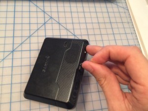
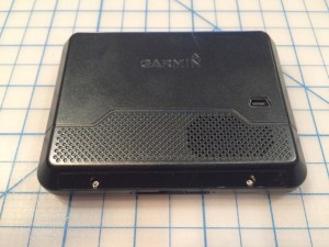
To disassemble this GPS unit, I began by trying to pry the injection molded plastic unit apart along the seams around the edge. It seemed like there was something more keeping the halves attached so I started exploring. After a couple minutes, I peeled off the sticker on the rear bottom of the unit to find 2 tiny torx screws!

IMG_4632

IMG_4633

IMG_4634

After removing the screws, I pried apart the case using a plastic spackle knife.

IMG_4636

IMG_4637

IMG_4638

I disconnected both the cables between the two halves – one goes to the LCD display and the other connects the front LED.

IMG_4640

IMG_4642

IMG_4643

There were 3 more phillips head screws on the main circuit board so I removed them to pull out the board.

IMG_4645

IMG_4646

IMG_4647

I disconnected the cable attached to the speaker and the cable attached to the battery.

IMG_4648

I carefully popped out the LCD display from the front bezel and removed the surrounding foam.

IMG_4650

IMG_4649

IMG_4651

IMG_4652

The only other remaining parts to remove were the speaker and battery. I pulled the speaker off from the housing pretty easily but struggled with the battery as the adhesive was so strong it was pulling the battery apart. I decided to just leave it.

IMG_4658

IMG_4659

IMG_4660

IMG_4661

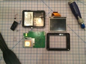
And here are all the parts removed!

IMG_4665

After finishing removing all the parts, I wanted to dig a bit further into the circuit board so I pried up the metal covering the GPS unit. It involved a lot of pulling with some pliers. Then GPS cover had a long rivet that was soldered through the board so I ended up having to force that apart with some force.

IMG_4654

IMG_4655

IMG_4666

I also removed the metal covering the logic portion of the board on the other side.

IMG_4667

IMG_4668

IMG_4671

Here are all the functions of the board that I could determine.

IMG_4669

IMG_4672

Overall the process wasn’t too difficult, once I first found the screws to open the unit. I thought that covering the screws with the sticker was an interesting design choice and certainly would deter some people from trying to do their own repairs on the unit. I also like the flexible circuits they used between the two halves of the unit, between the display and the main board. It makes sense to not have a rigid connection in order to easily repair the unit and allow for some relief.

Week 3 Homework

Hey everyone,
For class on September 24th, the homework is as follows:

-Complete circuit #2 and circuit #6 from the Experimenter’s Guide for Arduino booklet. Post a video of the circuit working to the blog by 10pm on Sept. 23rd.

-Read about For loops on page 61 of the Make: Getting Started with Arduino book.

-Finish the teardown and post to the blog by 10pm on Sept. 23rd.

Have fun!

Class Introduction – Josh Corn

IMG_0019

Hello everyone,

My name is Josh Corn and I am super excited for this making studio. I grew up in Sarasota, FL and went to school in Philadelphia. My background is in architecture and theatre design and I worked as an architectural consultant in Chicago for about 3 years. Most recently, I started a publication and traveled for a year collecting and producing online stories. My hobbies used to include woodcarving, rock climbing and paragliding but now that I am in the city I am trying to just ride my bike as much as possible. Check out my instagram at joshcorn2!