My instructable is online.
Author: lindpaintner
Julia’s Draft Instructable v. 1
Hello! Here is my very preliminary draft. I will update this to reflect some of the very helpful feedback I got.
——————————–
LEAVE A MESSAGE AT THE GOOSE
Audio recorder and playback system in the shape of a goose
INSPIRATION
My partner and I operate on very different and constantly changing schedules. He is a first year resident in Internal Medicine; I am a design grad student. Although we live together, we can go days without seeing each other. We would like to leave each other notes, but video messages on the computer and hand-written notes aren’t working for us. This device is mounted at my door and is an easy way to record a brief message on my way out that he can playback when he gets home.
FUNCTIONALITY
Record audio
Playback audio
Clear audio recordings
Indicate new message with LEDs
PARTS
Electronic parts:
Arduino Uno
Adafruit Wave Shield for Arduino Kit – v1.1
Electret Microphone Amplifier – MAX4466 with Adjustable Gain
AC Adaptor
Arcade buttons
LEDs
Wires
Resistors
Housing:
MDF
Glue
Screws
Paint
ASSEMBLY
Step 1: Put the parts together
Follow Wave Shield assembly instructions here
Mount the microphone and speakers (more TK)
Create a circuit for the LEDs and push buttons
Step 2: Write the code
Load the WaveRP Library
Write code to link the functions for recording and playing back to button functionality
Write code to create connection between message status and LEDs
Step 3: Build housing
Cut out the GOOSE PANEL (or your choice of image) from MDF using the scroll saw (or laser cut if you are doing something complex)
Create shallow box to attach to the back
Sand and finish with paint*
* The housing can certainly be made of many materials—I just used MDF for this example because it is easy to work with and generally accessible
Step 4: Putting it all together
Mount the board to the back of the goose in the box
Thread the button and LED elements into the front of the goose in the designated places
PLUG IN!
“Whatever shall my final project be?” wonders Julia.
I didn’t have ANY ideas for a while. Now I have a bunch, but very little idea which are feasible… Here goes!
Idea #1: Expand on the innovative switch project
I did like my bike brake light and turn signals, and think that it could be a quite useful thing, and fun to make work really well and be a believable add on to bikes. That said, because I currently don’t bike at all, I’m a little less excited. If I did this, I would want the system to be as elegant and minimal as possible, so I see there being some different sensors involved, but I’m not sure the code would change significantly.
Idea #2: Leave a message at the door
My boyfriend is a first-year resident at Mount Sinai hospital. I’m in this program. So obviously, we’re seeing a LOT of each other. (Not.) We have tried leaving notes or videos for each other—especially during weeks when he works the night shift and we literally can go a week living in the same apartment without seeing each other—but it’s always a little annoying to find paper or take the time to make a video. I was thinking I could create something that is mounted on the wall that you can record short voice messages on, so that each time one of us left, we could leave a message for the other.
Idea #3: Feel the wind
Wind is awesome. Fans are not. I was wondering if I could hack a fan that has multiple settings and can turn side to side, and program it to run through a series of settings and positions to simulate a more random wind experience. No idea if I could really do this, and it sort of already exists…
Idea #4: Get up and run
I always feel better if I start the day by moving—whether it’s a run, a walk, whatever. And yet, it is SO hard to do that when you just woke up. I was thinking of making an alarm clock that you turn off by putting on your sneakers. OR it could be hooked to a GPS, so you would have to get out the door before it would turn off… (I live in a 6 floor walk-up, so that would probably do it for me.)
Idea #5: I just wanted to hear your voice
Sometimes you don’t have time or can’t get in touch with someone you love, but you really want to hear their voice. My dad travels all the time and is always in some other time zone, so we don’t talk on the phone much. I was thinking of making some sort of small object that could be manipulated in a few ways (squeezed, shaken, pushed?) and playback pre-recorded messages from me, my sister, and my mom.
I have a few more ideas, but I’ll leave it at that. I look forward to getting some reactions!
I got the servo down
I chose to do Sketch 04 from our booklet, the Servo Sweep.
Setting up this initial code and circuit was easy enough, but I then struggled to set up the slight modification with the potentiometer. I tried and tried and wrote the code and copied the code, and consulted the Adafruit tutorial, and hooked it up to outside power (9V battery instead of USB), but no matter what I did, my servo arm just moved in sporadic fits and mostly stayed still.
FINALLY, I figured out the problem. I was trying to share ground and power between both the potentiometer and the servo. They are both three-pronged pieces, after all! How elegant!
EXCEPT that the order of the servo arms is NEG, POS, SIGNAL, but order on the potentiometer is NEG, SIGNAL, POS! So, I let go of my elegant four wire solution and separated the potentiometer and servo, and it worked like a charm.
Brake & Turn — Innovative switches for bike signaling

I used the innovative switch project to create a signaling mechanism for bikers. Traffic safety would be greatly improved if bikers had the same communication devices that an automobile has: brake lights and turn signals.
I had 4 actions I wanted to signal:
- Brake lightly
- Brake hard
- Turn right
- Turn left
I decided to translate “brake lightly” as a half-brightness of one LED when only one hand was braking, and full brightness with two LEDs if both hands are braking.
I began by writing the code. I set up a circuit with 4 inputs and 4 LED outputs, 2 red LEDs for the brake lights, 2 green LEDs for the turn signals. Because I wanted half brightness in the brake lights, I used analogWrite with the red LEDs. I wanted the turn signals to blink, so I used digitalWrite with delay. I used a series of if statements to declare the different states of the LEDs depending on the conditions read from the 4 inputs. Here’s the code:

Access the live text of my code here.
I tested it all at my desk just touching wires and troubleshot a few errors.

Then I headed over to use Josh’s bike (thanks Josh!) to test it all out installed. I mounted my Arduino board to the middle of the handlebars with some gaffers tape.

I set up the brake lights such that the lights would turn on when the brake was pulled, because that broke the circuit between the tips of the brake.

I set up the turn signals so that a simple piece of fabric on a glove, or a ribbon around the palm would create a bridge and close the circuit. That way, there are no wires connected to the person, and everything could be hardwired to the bike handlebars.

I used
2 red LEDs
2 green LEDs
4 10K Ohm resistors
4 560 Ohm resistors
a bunch of wires
copper tape
Here’s the demo!
Next step is to make my hand straps a bit more attractive and draw up my circuit diagrams!
This prototype uses LEDs on the Arduino Uno board, but in the final manifestation, the LEDs would be mounted to the bicycle itself, and all the wiring would be built into the handlebars. Obviously it is also not ideal for the board to be mounted to the middle of the handlebars and connected to the computer… but one step at a time!
Potentiometers, and photo resistors, and force sensitive resistors, OH MY!
Twist and shine
Glow in the dark
Dim under pressure
SATURN—It glows!!!
Hello Earthling! Welcome to my journey to space to discover the luminous Saturn, a planet both mystical and all too real.
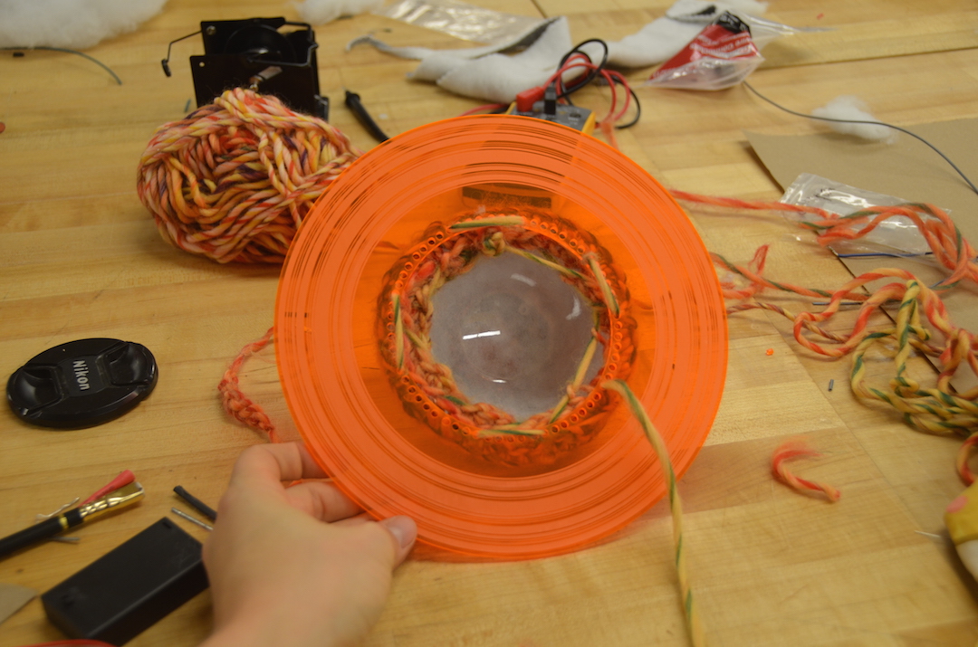
I began my journey with some multicolored yarn and a crochet hook, after attempts at sewing spheres proved too frustrating and unsatisfying. I crocheted two half spheres, lined them with fiberfill, and stretched them over halves of a plastic globe.


I had 8 white LEDs, with which I created a circuit running all of them in parallel off a 4.5V 3xAAA battery pack. The soldering was tricky, but I used a bunch of shrink wrap, and with a lot of guidance from our trusty TA Josh, I soldered 100 Ohm resistors to the negative legs of each LED, and then linked all the negative and all the positive ends to each other. It created a rather tidy little string of LEDS!


I created Saturn’s rings in Illustrator and laser-cut and etched them. I added some stars and tags for good measure… (those have yet to be implemented)

With my circuit complete, and my Saturn halves ready, I threaded the long leads through the top of one of the halves and used some electrical tape to situate the LEDS within the plastic globe. Then I sewed each half of the planet onto the middle acrylic ring piece and VOILA!


I give you: SATURN.

UPDATE:
Here’s my Saturn Nightlight explaining the inspiration for the project!
Late Night Light + Monster—Julia
Heart & Soul & DISCO

Teardown—LG Cosmos VN250—Julia

I took apart an old cell phone with a QWERTY keyboard. It was surprisingly simple—only held together by a 14 little screws and glue. Here’s the process:
I used only these three tools (and my fingernails):
- Phillips head screwdriver
- Flat head screwdriver
- Prying device

The back of the phone came off easily, and each subsequent layer just had a couple of screws and some adhesive to get through. As far as I could tell, everything in this phone was metal or plastic.
- Take off the back of the phone.
- Remove battery.
- Unscrew screws in the back.
- Remove the plastic covers for charging connection, micro-usb, headphones on the sides and bottom.
- Pry off the plate which holds this plastic to the QWERTY keyboard and reveal the logic board.
- Take off the buttons on the sides (volume, power).
- The metal piece covering the middle of the logic board can be removed to reveal the Qualcom QSC6055 processor. More on the logic board below…
- Unscrew two more screws to reveal the QWERTY keypad and plastic piece underneath.
- The LCD/Numeric Keypad Cable threads through a hole in the black plastic beneath the logic board. Unscrew two more screws and pry off this black plastic.
- Underneath that black plastic are the data connections to the screen and the front keypad. Carefully peel off the tape that holds the connections down and unplug them. The screen will lift out. The keypad is behind the data board.


GROUP SHOT!

Now, more on the logic board:

Here’s what I learned about all that a circuit board contains:
The circuit board holding microchips and processors inside a cell phone serves as the brains of the outfit. A digital signal processor, or DSP, converts an analog signal — your voice — to digital for transmission through the provider’s network. The DSP also converts a received digital signal to analog and moves the analog to the phone’s speaker and your ear. Radio frequency transmitters and receivers handle the signal as it moves to and from the phone. A microprocessor on the circuit board controls the phone’s various other functions, such as the keyboard and display. The phone’s operating system works from a memory chip, and the power management system keeps the device operating under battery power. A baseband chip serves as the phone’s antenna, grabbing and emitting digital signals when the phone is in use.
Here are all the parts I could identify:
- Qualcomm CPU QSC6055
- Micro SD slot
- 1.2 Megapixel camera
- Speaker
- Audio jack
- 3.7V Lithium-Ion Polymer Battery
- LCD screen
- QWERTY and regular keypad
- ZIF connectors
- Glued down cable ribbons
I couldn’t identify all the parts, but I did marvel at how simple the complex circuitry appeared.
I think the ribbon cable connectors are so elegant. It keeps everything very organized and clean (and flat), but the connections are very strong. I like the contradiction of these paper thin connectors and the power that is supplied through them. I’m always surprised by how sturdy and functional the connections are, especially on ZIF connectors.

I am also intrigued by the pressure sensors that are beneath all of the buttons. They are so sturdy, and the keyboard itself can withstand a lot of damage before the sensors beneath are affected.
