đź“·đź’ĄNicon D3 Teardown

đź“„ The introduction of Nicon D3 camera

the reason that why I chose the camera is because I really into taking photographs by using film camera as well as SLR camera. different from the silver salt reaction, SLR camera utilized the CCD(Charge-coupled device) and the CMOS to record light informations so that we can take pictures much more easily and spread the photos more easily. So i’d like to figure out how those electronic componds are arranged in the camera body to achieve those powerful founctions.

đź”§ The processes of assembly:

1 Remove all the screws that I can find

2 Use the heating gun to melt the rubber on the camera body.

3 Remove the screws under the rubbers.

4 Divide the camera into several parts.

5 Tear down the motherboard.

Here is the assembly process video đź”˝

⚙️ The main components of the camera:

✍️ my thoughts:

1 Nikon uses a lot of screws to connect different parts rather than using glue which makes the camera easy to take apart and easy to be repaired.

2 The body of the camera is made of magnesium which makes it as solid as a brick, all the parts are designed to use screws attach to it.

3 Robust surfaces, soft rubber on the grips, oversized buttons, locked controls, and environmental seals add up to a purposeful camera that has been designed with the requirements of the professional photographer in any situation.

Power Pants!

Power Pants are the pants that make you proud of getting dressed in the morning! They’re not your average pants. They provide you with a nice sense of accomplishment every time you put them on!

Coming soon to a store near you!


What’s in a Power Pant?!

The tech:

Power Pants are built on Arduino, using a simple piezo and pulse width modulation to create audio from chosen frequencies. What you see above is one of two functions coded into the Arduino. The second function is the longer musical bit you hear in the video at the top. It uses the contact in the same way to trigger the sound.

Here’s the code:

[code]
int ledPin = 13;
int inputPin1 = 2;
int inputPin2 = 5;
int val1 = 0;
int val2 = 0;
int counter1 = 0;
int counter2 = 0;
int speakerPin = 9;
char notesA[] = "azbC"; // a space represents a rest
int lengthA = sizeof(notesA);
int beatsA[] = {2,3,3,12};
int tempoA = 80;
char notesB[] = "Cbza"; // a space represents a rest
int beatsB[] = { 2,3,3,4};
int tempoB = 80;
char notesC[] = "gabygabyxzCDxzCDabywabywzCDEzCDEbywFCDEqywFGDEqi";
int lengthC = sizeof(notesC);
int beatsC[] = { 1,1,1,1, 1,1,1,1, 1,1,1,1, 1,1,1,1, 1,1,1,1, 1,1,1,1, 1,1,1,1, 1,1,1,1, 1,1,1,1, 1,1,1,1, 1,1,1,1, 1,1,1,1, 1,1,1,1, 1,1,1,1};
int tempoC = 150;

void setup() {
pinMode(speakerPin, OUTPUT);
pinMode(inputPin1, INPUT);
pinMode(inputPin2, INPUT);
Serial.begin(9600);
}

void loop(){
val1 = digitalRead(inputPin1);
val2 = digitalRead(inputPin2);
if(val1 == LOW && counter1 == 0) {
counter1++;
for (int i = 0; i < lengthA; i++) {
playNote(notesA[i], beatsA[i] * tempoA);
}
}

if(val1 == HIGH && counter1 == 1) {
counter1 –;
for (int j = 0; j < lengthA; j++) {
playNote(notesB[j], beatsB[j] * tempoB);
}}
if(val2 == LOW && counter2 == 0) {
counter2++;
for (int k = 0; k < lengthC; k++) {
playNote(notesC[k], beatsC[k] * tempoC);
}
}
if(val2==HIGH && counter2 == 1){
counter2=0;
}

else{ digitalWrite(speakerPin, LOW);

}
Serial.print(counter2);
}

void playTone(int tone, int duration) {
for (long i = 0; i < duration * 1000L; i += tone * 2) {
digitalWrite(speakerPin, HIGH);
delayMicroseconds(tone);
digitalWrite(speakerPin, LOW);
delayMicroseconds(tone);
}
}

void playNote(char note, int duration) {
char names[] = {‘c’, ‘d’, ‘e’, ‘f’, ‘g’, ‘x’, ‘a’, ‘z’, ‘b’, ‘C’, ‘y’, ‘D’, ‘w’, ‘E’, ‘F’, ‘q’, ‘G’, ‘i’ };
int tones[] = { 1898, 1690, 1500, 1420, 1265, 1194, 1126, 1063, 1001, 947, 893, 843, 795, 749, 710, 668, 630, 594 };

// play the tone corresponding to the note name
for (int i = 0; i < 20; i++) {
if (names[i] == note) {
playTone(tones[i], duration);
}
}
}

[/code]

IMG_0744IMG_0746 IMG_0745

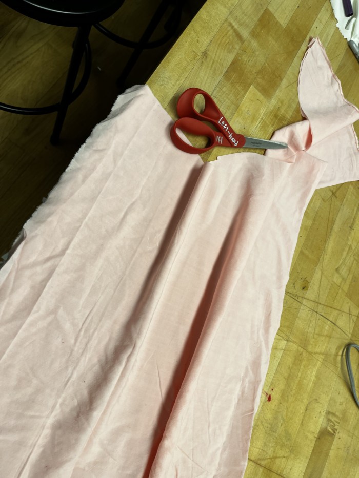
The simple wire contact activation was converted to a switch using conductive thread stitched into the button holes and around the button. This way, the button itself acts as the switch.

IMG_0747

For the demonstration, extensions were added out the legs where the audio would normally be wired directly into the Power Pants themselves.

This is the future of pants!

Gameboy Color TEARDOWN!

FullSizeRender 21

The Gameboy Color in Teal!

The only tool and technique you will need to open this is a small flathead screwdriver and, well… screw driving skills.  There is some finagling with the external screws, but you can get it!  It’s pretty simple and compact in there!

On that note:  Two interesting things!  One, It’s super compact with lots of hard soldering on the inside.  I point this out because I think it’s a huge factor in what makes it feel like a simple object on the outside, molded to closely contain everything inside.  The other is what you will later see int he buttons.  They’re just silicone rubber and molded plastic!  I was hoping to find some button I could appropriate, but instead, just little nubbins!  But I suppose this was done to save on damageable parts and space, making the contact points directly in the fiberglass board.  Anyway, read on!  It’s kinda neat how simple it appears on a large scale, but how complicated it is on the board.

My guess is the casing you see is injection molded.  Flip it over and look at the back.

FullSizeRender 22

You’ll have to remove these ridiculous tri-wing screws with a tiny flathead if you can’t get a tri-wing driver in a timely manner.  That’s what I did.  You have to jimmy them around until they slowly turn with the weak torque you can provide.  (P.S.  My gameboy was missing it’s battery case.  I used aluminum tape for years…  AA batteries.)

FullSizeRender 4

Pop the case off!

FullSizeRender 25

FullSizeRender 5

Then this plate from the back side that holds the game steady in the access point with four phillips head screws.  Plate appears to be stainless.  All the screws look like galvanized steel.  Three on the interior may be brass.  But it is unclear

FullSizeRender 8

Now look at the fiberglass circuit board.

FullSizeRender 9

It’s held into place by three phillips screws.  These are the ones that may be brass.  Pull those out and you can pull out the board and flip it!  Note: At the top of the board is the connection point for the game cartridge.

FullSizeRender 13

FullSizeRender 14

Before you remove the board, detach the LCD screen. There are little black switches to pop out on either side of that red tape. Then just pull out the tab.

FullSizeRender 7

Board removed:

FullSizeRender 17

This reveals the active side of the speaker that plays MIDI tones in the bottom right hand of the board, and the underside of the buttons on the face of the gameboy. FullSizeRender 10

FullSizeRender 11

Also removable is the cover of the power button and the infrared sensor cover.

FullSizeRender 23

Power Switch

FullSizeRender 18

Infrared on right, power indicator in red LED at top.

FullSizeRender 12

Power switch and LED covers both present on the side of the object (left to right).

FullSizeRender 20

The black dots on the back of the buttons appear to be magnets or something conductive to make contact with these components in the white portion of the board.

FullSizeRender 6

Here too is the volume knob.

You can remove the LCD screen with a black foam padding on the back by prying it lightly with anything flat and sturdy with rounded edges (so as not to damage the thin steel casing).  I used a really old flathead screwdriver that wasn’t sharp at all.

FullSizeRender 16

FullSizeRender 24

The LCD Screen.  That’s the last part to remove!

Other parts on the board include a lot of hard soldered stuff.

FullSizeRender 19

This includes an optical inverter (right), the CPU (center), regulated power supply module (top left), SHARP chip of some identifiable kind based on number (center left), and an integrated circuit (bottom right).

And here it is all exploded and knolled!

FullSizeRender 4

Thanks for looking!

-Will-

Will C. Lentz

Hello, Everybody!413322_2109191122390_719747228_o

I’m a maker with a background in a variety of materials including steel, wood, and ceramics. I’m originally from central Arkansas, but most recently moved to Brooklyn from a small craft school in the Blue Ridge Mountains in Western North Carolina. Experimenting with new materials and processes is one of my favorite things.  I also really enjoy good food and good tea.  Before a recent injury, you’d likely find me playing Ultimate when I wasn’t working, eating, or sleeping.  I’m working on that and I’ll be on the field again soon!

mr indecision

a small felt version of myself that turns its head and looks at you.

[Instructable here]

This is a project on using 123D Catch to get a 3D scan of my whole body. Once I had the scan I cleaned it up and manipulated it ready for 123D Make. I sliced the model in Make and preped it for Laser cutting. Once done I lazer cut and integrated the componentry and Arduino to make the head turn. I created two functions an automatic tracking function and a manually controlled function through Max MSP. In a way this is a Modern Day Puppet.

Code below the jump:
Continue reading “mr indecision”

Cloud

Advances in physical computing and interaction design hardware over recent years have created a new breed of smartobjects which are gaining more and more traction in the design world. These smartobjects have the potential to be far more interactive and emersive than ever before. What is exciting is that its becoming increasingly easier and cheaper to become a part of, with DIY and hacker communities initiatives such as Maker Faire, Instrutactables as well numerous other organisations & people showing the growing interest in this area. Done as part of the Making Studio Class taught by Becky Stern in the Products of Design Masters Program at School of Visual Arts. This project aims to capture the essence of this style of designing, where ideas, thinking and process are shared for others to use and expand on.

On one hand ‘Cloud’ is an Arduino controlled, motion triggered lightning & thunder performance. On the other it is a music activated visualizer & suspended speaker unit.


The cloud is made by felting hypoallergenic fiberfill to a sponge casing which forms the frame of the cloud and holds the speakers and componentry. The felting tool used is a custom made felting tool made from the left over sponge and 4 felting needles. To control the functions of the cloud there are three tactile switches scattered around the base. The concept references real clouds which constantly change shape through the switches requiring constant exploration to find the right switch to turn the right feature on or off.

Acting either as a semi-emersive lightning experience or as speaker with visual feedback this Nightlight – Nightspeaker hybrid introduces not only a new discourse for what a nightlight is or cloud be but also what a smartobject is or could be?

The Cloud

Work in progress, after days of working to get the separate components of the cloud working independently I now have them working together in the same arduino sketch. The components I am using are the the PIR sensor, the Wav Shield & LED Storm. My system does thus: The PIR sensor is triggered by motion > then the randomized Lightning sequence begins in a randomized cycle followed by a super lightning strike > milli seconds after the super lightning strike is a randomly selected thunder sound, the cloud then waits until the PIR is triggered again.

Lightning Cloud Test

Here is my code thus far: Continue reading “The Cloud”

Junk-Mail Phone Case/Dock by Richard

Introducing the “ijunk” – the junk mail iphone / ipod dock

“the best thing to happen to iphone since iphone 5”

When an iphone or ipod is docked it activates a junk mail delivery mechanisim. This was a really project with no apparent purpose but gave me the opportunity to use a physical imput to create a digital action in the ardino code and then return a physical output. The physical circuit uses a tip120 transistor which acts as a electronically controlled switch allowing the motor to draw power from an independent power supply. This is important as if the motor were to be connected directly to the arduino it could fry the arduino’s chip. The code i used was a version of the button example featured in the continue reading section of this post. Ideally if I had more time I would have better integrated the iPhone charging into the arduino and have it actually recognized when it was being docked, rather than just using the phones casing to connect the circuit via contacts.

Some of the tutorials and useful sites I found and used are here:

ijunk dock

Junk Mail Phone Dock from Richard Clarkson on Vimeo.

Code: Continue reading “Junk-Mail Phone Case/Dock by Richard”

Project One: Vegan Phone Dock

Research, Tutorials and Hacks:

The Vegan Iphone Dock:

This is an iphone dock designed specially for vegans. It is based on multi level Kit-set distribution model. The highest level is the Deluxe kit, with comes with everything needed excluding the fruit and crate. The Standard kit requires the user to find, hack or purchase a dog clip, copper wire, galvanized wire, fruit and a crate. There is also a free demo that shows hacker-vegans to make the entire kit from scratch by themselves.

The system works of a fairly well know chemical reaction that causes ions to move when the citric acid comes into contact with the zinc on the galvanized wire. Although sometime the iphone doesn’t indicate that it is charging it actually is, just at a much slower level than is required to switch on the charging indicator. Over time the fruit and wire will need replacing but that is the fun of the kit.

The kit was designed to suit a range of vegans from ‘standard vegans’ to ‘ultra vegans’ who criticize anything that removes natural landscapes and habitats from animals, sometimes this includes conventional electricity systems, thus the v-dock was born.

Coming to Etsy late 2013 starting at $49.90 + shipping.

Context Image 1.

Context Image 2.

Main Image 1.

Main Image 2.

by Richard Clarkson