Teardown: Nintendo Entertainment System

For our first project I decided to teardown a Nintendo Entertainment System, which I found at the Lower East Side Ecology Center Reuse Store in Gowanus, what a great place!

8_small

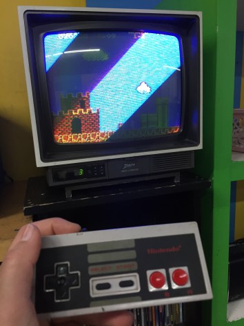
Aside from dropping off a bag full of old cables and some broken speakers; I had the privilege of walking around with one of the workers there, Carlos Cabrera. He showed me around the prop isles and some back isles where there were some things that he thought could be interesting to teardown. It was a hard choice, but I decided to go for a Nintendo, since it was the first video game I played with as a child. This one was damaged by a spill. Fun fact: the store has a functional one in the front that visitors may test out, I got to play Mario Bros for a couple of minutes   =)

2

The teardown was fairly easy, I used 2 small screwdrivers and a pair of pliers. Clic on the pictures below to see the full progression with some explanations along the way.

One thing that I noticed while tearing down the Nintendo is what caused the unit to break. A liquid of some sort must have spilled on the unit, and seeped through the top vents into important parts of the circuit board. The gravity of the damage could have easily been avoided if the vents would have been designed on the sides or back of the unit. While researching, I also came across people who complained that the way the games hooked into the machine,  it is delicate and prone to problems. Not only did dust interfere with the video game (most of us can remember having to blow on the game before inserting it!), but if any of the prongs were bent out of shape, the whole part had to be changed. In the last picture of my slide progression you can see it, it is the black plastic part right above the circuit board.

The experience of tearing down an electronic was pretty fun, researching the parts also yielded some interesting insights about this product, I am still in awe with the complexity of the circuit and I am looking forward to learning more about circuits and programing with Arduino. Thank you!


Gameboy Color TEARDOWN!

FullSizeRender 21

The Gameboy Color in Teal!

The only tool and technique you will need to open this is a small flathead screwdriver and, well… screw driving skills.  There is some finagling with the external screws, but you can get it!  It’s pretty simple and compact in there!

On that note:  Two interesting things!  One, It’s super compact with lots of hard soldering on the inside.  I point this out because I think it’s a huge factor in what makes it feel like a simple object on the outside, molded to closely contain everything inside.  The other is what you will later see int he buttons.  They’re just silicone rubber and molded plastic!  I was hoping to find some button I could appropriate, but instead, just little nubbins!  But I suppose this was done to save on damageable parts and space, making the contact points directly in the fiberglass board.  Anyway, read on!  It’s kinda neat how simple it appears on a large scale, but how complicated it is on the board.

My guess is the casing you see is injection molded.  Flip it over and look at the back.

FullSizeRender 22

You’ll have to remove these ridiculous tri-wing screws with a tiny flathead if you can’t get a tri-wing driver in a timely manner.  That’s what I did.  You have to jimmy them around until they slowly turn with the weak torque you can provide.  (P.S.  My gameboy was missing it’s battery case.  I used aluminum tape for years…  AA batteries.)

FullSizeRender 4

Pop the case off!

FullSizeRender 25

FullSizeRender 5

Then this plate from the back side that holds the game steady in the access point with four phillips head screws.  Plate appears to be stainless.  All the screws look like galvanized steel.  Three on the interior may be brass.  But it is unclear

FullSizeRender 8

Now look at the fiberglass circuit board.

FullSizeRender 9

It’s held into place by three phillips screws.  These are the ones that may be brass.  Pull those out and you can pull out the board and flip it!  Note: At the top of the board is the connection point for the game cartridge.

FullSizeRender 13

FullSizeRender 14

Before you remove the board, detach the LCD screen. There are little black switches to pop out on either side of that red tape. Then just pull out the tab.

FullSizeRender 7

Board removed:

FullSizeRender 17

This reveals the active side of the speaker that plays MIDI tones in the bottom right hand of the board, and the underside of the buttons on the face of the gameboy. FullSizeRender 10

FullSizeRender 11

Also removable is the cover of the power button and the infrared sensor cover.

FullSizeRender 23

Power Switch

FullSizeRender 18

Infrared on right, power indicator in red LED at top.

FullSizeRender 12

Power switch and LED covers both present on the side of the object (left to right).

FullSizeRender 20

The black dots on the back of the buttons appear to be magnets or something conductive to make contact with these components in the white portion of the board.

FullSizeRender 6

Here too is the volume knob.

You can remove the LCD screen with a black foam padding on the back by prying it lightly with anything flat and sturdy with rounded edges (so as not to damage the thin steel casing).  I used a really old flathead screwdriver that wasn’t sharp at all.

FullSizeRender 16

FullSizeRender 24

The LCD Screen.  That’s the last part to remove!

Other parts on the board include a lot of hard soldered stuff.

FullSizeRender 19

This includes an optical inverter (right), the CPU (center), regulated power supply module (top left), SHARP chip of some identifiable kind based on number (center left), and an integrated circuit (bottom right).

And here it is all exploded and knolled!

FullSizeRender 4

Thanks for looking!

-Will-