The modem is primarily made of plastic for the outer container, and contains metals like copper and aluminum in its internal electronic parts. The circuit board is made from fiberglass, gold and other materials.
The electronics all exist on a single circuit board.
Tools Used: Hands Small screwdriver Pliers
Technique To me, the takedown for this felt rather straightforward.
1. I used pliers to peel back the sticky tabs (feet) on the bottom of the modem 2. I used the screwdriver to take out the small screws holding the body together. Then I used my hands to pry open the body which revealed the circuit board. 3.I used my pliers to cut the rubber screws holding the Cable Modem chip in place, which released the springs and allowed me to remove it -> pictured below.
Parts Note: I found it a bit difficult to find the exact model of my modem online, so I used similar devices to try and identify the electronic parts.
I inserted the quote below to provide context around the parts that I could not identify.
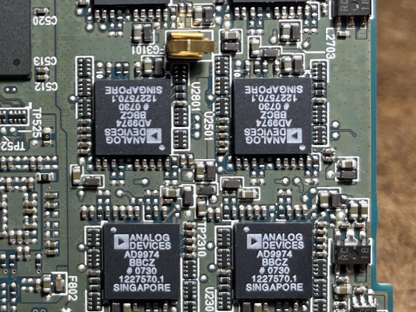
“The cable modem chip connects to two memory chips, one a synchronous DRAM, the other a Flash. The flash chip lets the cable company change aspects of the subscriber’s internet service without actually changing any hardware. In that regard, the flash chip holds configuration data and comes into play, say, when a cable subscriber buys more download speed from the cable company.” – https://www.microcontrollertips.com/teardown-inside-cable-modem/
To kick off my teardown of the A1673, I needed to remove the screen. I used a heat gun to loosen the glue, while gradually prying off the LCD Assembly using a palette knife. Removing the thin aluminum shield in the top left allows access to four very tiny screws. Once unscrewed, the screen can be detached and set aside. Diving deeper involves more tiny screws, flex cables (careful, they’re paper thin!) and adhesive-backed static dissipative foam.
Every iPad is made by Foxcomm, by both factory workers and machines. The plastic housings are made through precision injection molding.
ToolsNeeded
Heat gun
Pry tool
Small phillips screwdriver
Components
Screen Assembly and Housing
The iPad Pro’s screen assembly is comprised of the front panel/glass, touch screen digitizer, and LCD display. The glass–believed to be aluminosilicate–is polished with cerium oxide and glued to a plastic frame. The LCD is made from liquid crystals, and is housed between two polarizers.
The back case is CNC milled from a solid block of aluminum. In order to achieve its matte, scratch-resistant finish, the piece is anodized and sandblasted.
Note: Although highly recyclable (and Apple reuses aluminum from disused products when creating new housings) the difficulty in extracting aluminum from the earth means that it uses a large amount of fossil fuel.
Battery and MotherBoard
The lithium-ion polymer battery takes up more space than any other component, and is pressed into the housing of the iPad by machine. The process of creating these batteries involves combining lithium with a metallic oxide catalyst, a dry solid polymer electrolyte and a metallic current collector. First, a lithium ingot is pressed and laminated until it is formed into a length of thin metallic sheet. The sheet is then spool-wound and baked in a vacuum oven to self adhere. Finally, the battery is sent off to a fabricator to be electrolyzed.
Close-up of the A9X Chip
Apple’s A9X Chips, manufactured exclusively by Taiwan Semiconductors, used a 16nm FinFET lithography process.
Speakers, Cameras, Power Button Assembly, 3mm Headphone Jack, and Home Button Assembly
Full disclosure–the flex cables broke and when removing the power button assembly, and is only partly pictured here. It shares a flex cable with the microphone, power button switch, flash, and ambient light sensor. The home button features a touch-sensor and is sealed with a soft rubber gasket.
Both rear (top) and front (bottom)-facing and cameras use scratch-resistant glass, and are sealed to the frame with either rubber and foam gaskets.
Upper and lower speakers
The A1673 features 4 speakers–two are located in either side of a long plastic bar housed below the top frame. All four speakers are housed in plastic, and sit below the same ESD foam-covered aluminum plating used to protect other components.
Apple is notoriously secretive about their manufacturing process, and so it was hard to understand as much as I would have liked about some of the components. I’ve worked on some of the earlier gen iPhones, so had a fair idea that I’d run into plenty of flex cables and lots of glue.
Notable Design Elements
Ever since Apple introduced flash drives into their products, the interiors only get more minimal and more sleek–it’s almost artistic. No zip-tied cable nests, no loose logic board held in place by a wish. Hardly any component infringes on another’s real estate. The placement of the batteries are reminiscent of an aerial view of midwest crops, and the logic board like that of a city at night. This could be for two reasons. Firstly, because it’s Apple, they over engineer the inside, so that the outside can be simple. And secondly, they know consumers pay attention to the inside of their products, so it’d better be beautiful.
I always notice the flex cables. Being paper thin makes them ideal for iPads and iPhones, and it also makes them stackable. You can have multiple overlapping cables take up just a few millimeters, and their wide surface makes them ripe for being glued down when needed.
Thanks for reading! Feel free to watch the teardown below 🙂
Tools: Phillips and flathead precision screwdriver
Step 1: Opened the back of phone, and removed the battery
Step 2: Used Phillips and flathead precision screwdriver to remove all screws on the back of phone
Step 3: Removed camera and microsd card
Step 4: Used screwdriver to lift off back, which revealed the wiring and a very strange smell 🤨
Takeaway: It was interesting to see how many moving parts there are within such a small device. I’ve always been curious as to what exactly are the components allowing us to view images, make a call, save data… Doing this experiment has certainly piqued my interest even more than before.
Welcome to the tear down of the Lomi Massage Gun! It is your average 30 dollar massage gun from Walmart. I was excited to figure out how something so uniquely shaped on the outside would look on the inside.
TOOLS:
Small Phillips Head Screwdriver
To start, I observed six screws on the outside of the gun and unscrewed all of them. The massage gun popped right open, and I was able to carefully take out all of the parts.
Turns out, there are not that many parts inside, making the outside more complex than the inside.
PARTS:
3 Different Plastic Massage Heads
7 Small Metal Screws
1 Massage Control Board (AKA Motherboard)
1 Micro USB Battery
1 DC Motor
1 Silicone Power Button
1 Massage Gun Plastic Shell
DESIGN CHOICES
The massage heads are interchangeable using a Push-and-Pull Mechanism. This allows for ease of use, reliable products, cost effectiveness, and any other push-and-pull head can be inserted into the gun.
The Massage Control Board was secured in place at the top of the gun by slipping between two plastic ledges that held it. This was interesting because the battery and motor were really heavy, and would crush the motherboard if it was on the bottom.
The JBL Speaker looks very seamlessly integrated from outside with zero screws. So I used a file and a hammer to pry the curved perforated metal front off to examine further.
I broke off the soft silicon pads on the bottom of the speaker and smashed open one end.
I tried to pry off buttons from the other end to reveal inner structures, then used it as a breaking point to pry open the exterior shell. The exterior shells turned out to have three layers and screwed to the black inner part in an invisible way (screws were hidden behind the two round pads at the ends).
Breaking down the innermost part was very painstaking. I first unscrewed all the screws I could find only to realize the halves of this chunk seems tightly glued along the middle line. I tried to pry it open from multiple angles with no luck. Inspired from the teardown videos of other JBL speakers, I managed to find a hidden screw located at the central back and via here was finally able to break it open.
Here’s what’s at the heart of the JBL Speaker: a tube, some damping foams, two speaker drivers, one main circuit board, and one lithium battery underneath.
Here’s the final look from the JBL teardown with labeling.
Two Interesting Designs
Bass Reflex Tube
How it works: when the speaker is on, the speaker drivers push air through the tube to the outside. The shape of the tube is also carefully designed to resonate in a way that boosts lower frequencies and improves bass response.
Three-Layer Outer Shell
The three layers tightly bind with one another and add extra colors & textures to the speaker’s exteriors. They also provide stronger binding for the relatively delicate inner part and protect it from potential impacts. I also think their particular shape acts as a weight balance for the speaker to stay flat on the table with the perforated steel front always facing forward.
Tools & Techniques during Teardown
Tools
Techniques
Pliers of different sizes
Screwing/Unscrewing
Cutting plier
Prying
Files of different sizes
Smashing (attempted)
Philips screwdriver
Component & Material & Manufacturing
Component
Material
Manufacturing Technique
Perforated Steel Front
Perforated Steel
Sheet Metal Punching, Stamping
Outer Shell (Three-layered)
Plastic (ABS/Polycarbonate)
Injection Molding
Round End Caps
Plastic (ABS or Polycarbonate) with Rubber Inserts
Injection Molding, Overmolding
Speaker Drivers
Diaphragm: Mylar/Polypropylene, Frame: Metal (Steel/Aluminum)
For this exciting assignment, I’m tearing down the Wemo Maker. It looks like a WIFI Extender but it’s actually a device for smart home integration. It allows DIY enthusiasts to remotely control low-voltage devices through an app, such as blinds, sprinklers, powered gates, etc.
Here is a list of tools I used and the process:
1, Wire cutter (failed):
The casing of this device consists of a box and a cover plate with no screws on it. So, I first tried using a wire cutter to cut open the casing, but the plastic had become brittle, and I could only cut off the edges.
2, Drill:
Then I tried using a power drill to make holes onto the casing so that I would have a place to pry it open. After succeeding, I found that the cover plate was glued into a precise slot in the casing, making the device appear seamless and preventing people from opening it.
3, Utility knife:
The PCB board and some wires were fixed inside the box with hot glue, and I used a utility knife to separate them. (I was surprised that they use hot glue. Such a convenient way, isn’t it?)
4, Hex screwdriver:
Next, I removed the screws that were securing the PCB board to the casing.
5, Hands:
I pulled some wires connected to the board by hand. This step was easy.
6, Wire cutter again:
Since some electronic components were soldered onto the board, wire cutters were perfect for cutting off their pins.
Hello! The MOLE is the all-in-one network camera for security and all your social network communities. A simple 3-step setup gets this Wi-Fi camera up and running so that you can automatically send video clips to YouTube, even if you’re not there. Sophisticated built-in motion detection controls what you record, and will notify you via Twitter or email if the Mole catches something. You can remotely control the pan & tilt angles, and monitor or record video from anywhere in the world.
I was thrilled to break its parts down to see what this camera could see. For starters, an SD card came with !!
(unfortunately no footage on it)
This is the outer shelling of the camera as well as the body
Materials Used
Plastic: Many surveillance camera housings are made of durable plastic materials that are weather-resistant and lightweight.
Cables: Cables used in the camera may contain copper conductors for data and power transmission, surrounded by insulation materials.
Electronic Components: The internal components of the camera, such as the printed circuit board (PCB), image sensor, and other electronic parts, are typically made of various electronic materials, including semiconductors and conductive materials.
Rubber Seals : To make them weather-proof and moisture proof
Mounting Hardware: Mounting brackets and screws may be made of metal or sturdy plastic, (injection moulding)
Glass or Acrylic: The camera lens cover was made of glass or acrylic to protect the lens
Plastic or Rubber Grommets: These are used to seal cable entry points and prevent water ingress.
Manufacturing Techniques Used
Injection Molding
Metal Fabrication
Soldering and PCB Assembly
Lens Installation
Infrared (IR) LED Integration
Software/Firmware Installation
Tools used
Micro Screwdrivers
Regular Screwdrivers
Hammer
Chisel
Interesting Design elements
I was surprised to see not too many screws on the inside and multiple locking mechanisms to ensure there was no way water or dust could enter the camera. The build was super sturdy and pulling the two (Base & Camera) apart was definitely an issue.
The second thing that blew me away was the amount of tech and chips and dips in a product so small.
And the third is definitely have to be the Motorized Mechanisms (Pan, Tilt, Zoom) within the camera. Would love to learn a lot more!
Watch the moment I realized the Dromo Copter still (kind of) worked! I replaced the batteries in the remote control and charged the drone in hopes it might still work before I took it apart. Glad I did!
Teardown Instructions
Tools Needed: mini precision screwdriver, nimble fingers
Part 1: Remote Control
Unscrew the lid covering the batteries and remove
Unscrew the remaining two screws embedded on the left and right sides
Pull apart the top and bottom of the external case to reveal the control circuit
Pop out the 2 toggles and 3 button caps
Layout the pieces
Part 2: Drone
Pull off the kickstand featuring the product QR code
Pop off the 4 plastic propellers
Remove 4 screws and pull apart top and bottom of plastic casing
Extract the
Layout the pieces
Materials / Components / Product Information
Plastic
Metal
Fiberglass
Dimensions 7.5cm x 7.5cm x 3cm
Flight time: 6/7min
Battery : lithium polymer 3.7V 120mAh
Technology: quadcopter
Working frequency: 2.4Ghz with anti-interference circuit
Gyroscope: 6 axis
Control: 2.4Ghz radio control 2 x AAA
Interesting Design Elements
The circuit board in the drone matches the shape of the drone with holes on each of the 4 ends to hold the tiny motors in place. It catches your eye when you’re used to seeing a rectangular PCB.
This is more a grievance than interest – the screws were so tiny it was almost impossible to reach them and open the drone! I’m sure the rationale behind that decision is 1) so that the screws don’t distract from the overall design and 2) user’s are not encouraged to take apart the product.
the reason that why I chose the camera is because I really into taking photographs by using film camera as well as SLR camera. different from the silver salt reaction, SLR camera utilized the CCD(Charge-coupled device) and the CMOS to record light informations so that we can take pictures much more easily and spread the photos more easily. So i’d like to figure out how those electronic componds are arranged in the camera body to achieve those powerful founctions.
🔧 The processes of assembly:
1 Remove all the screws that I can find
2 Use the heating gun to melt the rubber on the camera body.
1 Nikon uses a lot of screws to connect different parts rather than using glue which makes the camera easy to take apart and easy to be repaired.
2 The body of the camera is made of magnesium which makes it as solid as a brick, all the parts are designed to use screws attach to it.
3 Robust surfaces, soft rubber on the grips, oversized buttons, locked controls, and environmental seals add up to a purposeful camera that has been designed with the requirements of the professional photographer in any situation.