Update: Manako’s final project

Project Description:
The project consists of curves that hang from a frame that change their shapes as they interact with the audience.  Various ropes (or wires or threads) will hang from the top of a frame/arch, creating different curves. Conductive thread is wrapped around these ropes, so that the ropes will function as capacitive sensors.  Once a rope is touched, it will turn on the motor that is placed on top of the frame and pulls the rope upward.
The effect is like playing a visual string instrument.
Material Exploration:
Below artifacts were hung from a drying rack to assess their materiality.
dsc_0132
  • fishing string
  • beading string wire
  • ball chain
  • laundry hanging string
  • yarn
  • nylon rope
  • 2 flower arrangement wires
  • jewelry chain
  • frame hanging wire
Ball chains made the best curves and they were conductive, making it compatible with capacitive sensoring system.
Motor Exploration:

Below motors were tested.

  • 5V DC motor
  • 12V Stepper Motor
  • Rotating Servo

DC motor doesn’t have sufficient torque to rotate the spool and pull the chain up.  The servo has good torque and it’s easy to use because of the wheels that attach to its shaft, but it makes an awful, high-pitched sound.  The stepper motor has the torque needed without the annoying sound of servos.

Secret Garden-Manako’s proposal for final project

My final project will be on the same trajectory as the stroking porcupine, my last project.  Using a capacitive sensing system, I want to create a vertical garden that represents one’s emotional wall.

Everyday, in our interactions with others, we gauge/warm up to/distance/trust/close off/let in others.  Similarly, pods of grass loosen/appear with a nice gentle stroke and hide behind the  with hard slaps.

Steps:

  1. Build a 12″x 12″ frame for a “wall” that stands upright
  2. Make a square insert of grass that would become the capacitive sensor
  3. Run conductive copper tapes in the back of the square and fill with dirt&grass
  4. Complete the circuit by connecting the copper tapes to Arduino shield
  5. Determine whether it’s a slap or a stroke by measuring the length of the touch with capacitive sensing grass
  6. Use a motor for pulling in the squares of grass when they’re slappedgrasstrolley


Grass wall retracts:


Still need to define how to make the grass square slide back and forward (servo? belt?).


Supplies

screen-shot-2016-11-21-at-12-16-22-pm     11435a12p1-h02d-abbr


OR ALTERNATIVELY….

nike-flyknit-collective

Manako’s Porcupine Stroke-Sensor Switch

My initial idea was to create a curtain of sliced materials that would work as a switch when stroked.

Original Sketch:

1555_001

To understand the best method for achieving this stroke effect, I researched pressure sensors, stroke sensors, and capacitive sensors:

notes_capacitivesensor

First prototype using aluminum foil as capacitive sensor:img_3733

Upon learning that the stroke sensor (illustrated above) could be combined with capacitive sensors, I decided to follow the steps below:

  1. Connect Arduino to conductive fabric
  2. Sew the conductive fabric to the base fabric
  3. Use conductive thread to stitch the two fabrics together
  4. Leave the excess conductive thread on the surface to be stroked
  5. Use the code for capacitive sensor to measure the electric field being affected by the stroke and use the measurements to instruct the arduino to turn on/off the LED.

Final product: a stroke-sensor porcupine whose LED eye turns on/off when it is stroked.

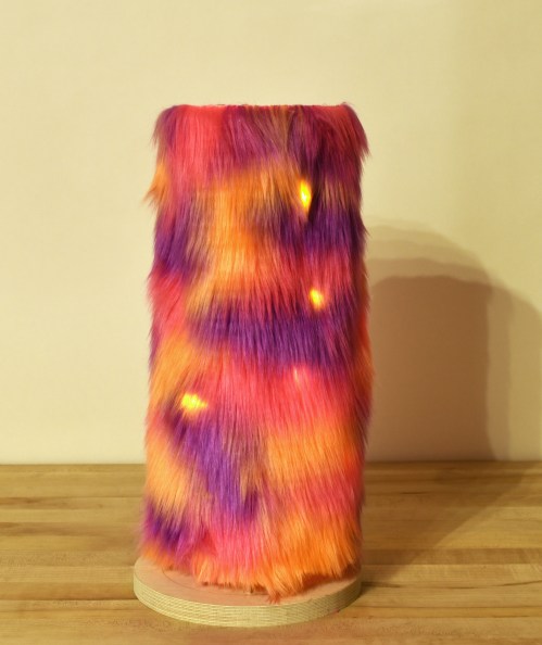
Plushy Lamp by Manako

Update 2:  Redid the circuit and got the lamp to light up!

My main takeaway from this project: know what I’m after, don’t get distracted by amazing plush.  My original goal was to experiment with light diffusion using acrylic rods and different placement of LEDs.  I should’ve known that the plush I chose for my final model was too thick to work with acrylic or LEDs placed at the core of the lamp.  Will not let amazing plush take me off-course next time!

dsc_0147


My original model did not light up. At first I thought:

The problem is with this parallel circuit.  Each individual set lit up fine before being soldered together, but when soldered together, they didn’t light up.  It’s probably because of the poor connection.  I’ll redo it and get it to work.

Update 1: Found out the problem.

I checked the circuit with a power supply and a conductivity meter.  It turns out the problem was not the connection but the LEDs.  I designed it to be 4 series sets of 5 parallel circuits, so they would resist each other, and no resistor would be needed.  However, I forgot that the whole series circuit was required when I plugged in just one set of 5 parallel circuits in the 9V battery, and this killed all the LEDs.

Rotating Lamp Prototype 1

Here is a video of my prototype.

I found that:

  • placing the LEDs on the lower end of the lamp makes the light diffuse better
  • I’ll need more LEDs
  • using multi-colors is okay (I thought it would look terrible)
  • just placing a disk on the bottom doesn’t make this shape rotate

For the final model, I will

  • use a fabric that is more hairy
  • place LEDs on the base board
  • cover the board with reflective material
  • figure out the mechanism for rotation (maybe use washers, a nut, and a bolt to make it rotate more smoothly)
  • change the shape of the tower to something more interesting when its rotated

Circuit diagram:
img_3248