Piggy Bank: Half Marathon Training Progress Lamp

As a reluctantly avid runner, I like to create incentives for me to stay on top of my running progress. For this project, I’ve created IFTTT applets and a lamp that does the following:

Screen Shot 2018-12-12 at 7.52.49 AM.png

Here are parts of the process below.  You can view the full instructions on my Instructables page

To start, I created an applet that logs every run in a Google spreadsheet.  In it, I edited the first 13 lines with formulas and benchmark numbersStrava Run Log.png

Once that was set up, I setup an Adafruit feed that collects data from IFTTT applets that are triggered every time I hit a certain benchmark.  Each time I hit a weekly benchmark, data unique to the week gets sent to my Feather Huzzah board and lights up the number of LEDs that corresponds to where I am in the training schedule

Strava to Google Sheets.png


Screen Shot 2018-12-12 at 8.12.49 AM.pngThen, I moved on to laser cutting and assembling the lamp.  I had the most fun while doing this!  IMG_5776.jpgIMG_5768-2.jpg

IMG_5767-2.jpg

Then, came the soldering.  IMG_5772.jpg

IMG_5773.jpg

IMG_5775.jpg

I actually had to re-solder the entire circuit using different LEDs because the sequins I got from Tinkersphere actually were not compatible with my code.  Luckily I had other RGB LEDs readily available and the second time around was much faster than the first! I ended up with a much cleaner circuit as pictured above.  (special shoutout to Oya of the VFL for staying with me until 1AM to help me troubleshoot.  You are an angel)

I’m so thrilled with the final product and will definitely be using this when training for my next race.

IMG_5782.jpg


Video Review

Hi team,

Here are the transcribed notes for the videos we viewed in class today!

Effective

  • Shows product being used
  • diagram overlay
  • combining close-up shots (detail) with medium shots (context)
  • Shot composition
  • Shows software workflow
  • Leads viewer to where to find more information
  • Tripod to stabilize
  • Shoot during daytime -> diffused lighting
  • Establishing shot
  • Giving/restricting “personality” of characters/objects
  • Surprise and humor
  • Music changes to fit theme

Distracting

  • Over-the-top acting
  • Too slow/fast
  • Hands shaking
  • Background noise / poor audio
  • Irrelevant music
  • Extraneous b-roll
  • Too long
  • Too much motion

More Internet of Things

This week, we continued our exploration in Internet of Things.

First, we connected an LED to Adafruit IO.  In the video below you’ll see that the app on the screen receives inputs when I press the button

In the next section of the assignment, the app sends me an email each time I press the button that also turns on the LED

We also added a neopixel into the mix by incorporating the Adafruit Neopixel library!

I also played around with a widget on my phone.  It was a little hard to take a video, but here is a snapshot of my phone screen

This next part was fun as well as we saw two circuits react identically to an input

Since I am still a little behind on the project, I will need just a little extra time to submit the BOM and circuit.  Will update shortly!

Huzzah! Internet of Things!

This week we got our feet wet with the Huzzah!
LED Test:

I also got the Huzzah to connect to the internet:

Button and LED:

Apologies for the late edit! Here are the 3 ideas for my project.  IMG_5382

The top idea involves a sensor that will let me know with a “happy” or “sad” face on a screen when my plants require watering.  I’ve been a very bad plant dad to poor Chloe, my money plant, so I think this intervention may be necessary for her survival.

The second idea checks the weather each day and gives me recommendations for things to wear or carry, such as an umbrella for rainy weather.

The last idea will search news feeds for mentions of Trump and let me know on days when I should actively avoid the news.  This could also be modified to open up a piggy bank so that I can treat myself on days that may be particularly depressing.

Flasher Costume


Last week for Halloween, I dressed up as a flasher.

This is sadly the only video I have of it in action since Victoria and I got separated from the group early on in the parade, but here are some additional pictures of the interior and exterior

IMG_5219.jpg

The exterior shell is a coat that I had designed, patterned, and made some time ago.

IMG_5215.jpg

I cut 6 segments of LED strips compatible with the neopixel library into 4 LED sections for a total of 24 LEDs, all connected in parallel.  The LED portion of the circuit was attached to the innermost layer of lining so that no stitching would be visible from the inside of the coat.  The second layer of lining was added to create light diffusion and to also hide the circuit.

IMG_5216.jpg

Through a small opening in the seam joining the right lining and facing, I pulled the rest of the circuit with the Gemma, lithium battery, and button through.  The Gemma and battery were inserted in a pouch I sewed into the lining, and the button was attached to the right front button hole for quick access.

Building the circuit was straightforward because I was able to preview it on TinkerCAD first.  The coding, however, was the trickiest part.  I had originally planned to use code from a library of LED strip effects that I had found on the web, but it was incompatible with the ButtonCycler example that I wanted to build on.  For this reason, I opted to use the sequences in the ButtonCycler, tweaking some of the delays and cycle times.


Costume WIP

For this week, I’m testing out components and also tweaking code in TinkerCad.  Since my partner works in lighting, I’m trying to take advantage of his treasure trove of leftover LED strips and parts.

As I was searching through his pile, I came across a bunch of LED strips but he let me know that they probably weren’t ideal since they were meant for FastLED.  I wanted to be able to practice working with the NeoPixel library, so I decide to rule these out.  Then, we found something really special…

He had a leftover NeoPixel library-compatible LED strip that glows in different kinds of white based on the different RGB inputs as well as a gorgeous amber color that you see in the video.  I went with this because these lights felt very emotional. My hope is that once I cut them up and spread them out throughout my lining fabric, the different kinds of white and amber will show.

To quickly show me the kind of light patterns that are possible, my partner hooked it up to industry-standard mapping software, called MadMapper.   Here’s a nifty video of it below:

To test out my circuit, I turned to TinkerCad

Brilliant Curcan-Robo.png

I referenced code from a nifty website that has code for a lot of different patterns.

Here’s my code for rainbow twinkles below:

 #include 
#define PIN 6
#define NUM_LEDS 48
// Parameter 1 = number of pixels in strip
// Parameter 2 = pin number (most are valid)
// Parameter 3 = pixel type flags, add together as needed:
//   NEO_KHZ800  800 KHz bitstream (most NeoPixel products w/WS2812 LEDs)
//   NEO_KHZ400  400 KHz (classic 'v1' (not v2) FLORA pixels, WS2811 drivers)
//   NEO_GRB     Pixels are wired for GRB bitstream (most NeoPixel products)
//   NEO_RGB     Pixels are wired for RGB bitstream (v1 FLORA pixels, not v2)
Adafruit_NeoPixel strip = Adafruit_NeoPixel(NUM_LEDS, PIN, NEO_GRB + NEO_KHZ800);
void setup() {
  strip.begin();
  strip.show(); // Initialize all pixels to 'off'
  
}

void loop() {
  TwinkleRandom(20, 100, false);
}

void TwinkleRandom(int Count, int SpeedDelay, boolean OnlyOne) {
  setAll(0,0,0);
  
  for (int i=0; i<Count; i++) {
     setPixel(random(NUM_LEDS),random(0,255),random(0,255),random(0,255));
     showStrip();
     delay(SpeedDelay);
     if(OnlyOne) { 
       setAll(0,0,0); 
     }
   }
  
  delay(SpeedDelay);
}

void showStrip() {
 #ifdef ADAFRUIT_NEOPIXEL_H 
   // NeoPixel
   strip.show();
 #endif
}

void setPixel(int Pixel, byte red, byte green, byte blue) {
 #ifdef ADAFRUIT_NEOPIXEL_H 
   // NeoPixel
   strip.setPixelColor(Pixel, strip.Color(red, green, blue));
 #endif
 #ifndef ADAFRUIT_NEOPIXEL_H 
   // FastLED
   leds[Pixel].r = red;
   leds[Pixel].g = green;
   leds[Pixel].b = blue;
 #endif
}

void setAll(byte red, byte green, byte blue) {
  for(int i = 0; i < NUM_LEDS; i++ ) {
    setPixel(i, red, green, blue); 
  }
  showStrip();
}

I had originally thought about having two separate strips coming out of different outputs so that the left and right side of the body could be doing different things, but I’ll be keeping it simple!

Here’s my To-Do for the next week:
Cut 2nd lining for coat
Cut LED Strips
Write switch into the code
Determine layout for all LEDs.  I think I will come down a bit in number of LEDs since 48 separate LEDs might be a bit much!  I may cluster some of the LEDs to reduce the number of solder joints I’ll have to make.  Still working on this part…
Sew circuit into my lining
Sew lining back into coat

I have quite a bit of work ahead but I’m really excited about this project, especially since my partner gave me really beautiful LEDs to work with.

Halloween Costume Sketches

I sketched up three halloween costume ideas this week.  I’ll be completing this project by myself.

My first idea is to create a black cropped crewneck sleeveless top with an array of red, orange, yellow, and white LEDs in the shape of a flame.  I would be wearing this with khaki pants to complete the costume for a matchstick.

IMG_4870.jpg

My hope is that I could make the LEDs glow in a pattern that evokes the burning of a flame.

Another idea I had was to dress up as a magic 8-ball.  There are various tutorials and code available online for a magic 8 ball, as shown in the video below

The LCD display shows a different “fortune” whenever there is a tilt sensor input, which I will embed in my costume so that it responds to my jumping.

IMG_4869.jpg

For the garment itself, I’ll make it a crewneck, black shift dress with a zip closure on the center back.  This way, I can keep it relatively simple and even have a pattern for a dress I could remake without the circuit.

My favorite idea is to be a flasher!  The idea is to wear a nude full bodysuit underneath a trench coat that has flashing LEDs on the lining of the fabric.  People would ask me what I’m dressed as, and I would open my trench coat revealing a flashing interior and what will, for a split second, will look like my nude body.  I have a trench coat in the works already and I would like to attached a second lining layer with an embedded circuit for this project.

IMG_4868.jpg
I currently have a trench coat that I have the pattern for.  I’ll cut out a second lining layer for the right and left front pieces and embed a circuit with an Adafruit GEMMA,  flora neopixels, and a photocell (to detect when the coat is open).  The idea is that I’ll program the neopixels to flash when the photo cell detects light.

Week 5 Homework

This week I had a chance to play with a potentiometer and motor for the rest of Lesson 3.  Here is my final product below!

It took a moment to get this one going but finally figured out that the transistor was oriented upside down. Once I switched that around I was able to get the motor running.  I also realized that before I put the purple tape on the motor, I actually could barely tell that the motor was running when it was running (haha).

Next, I was excited to get a neopixel strip to work using the Arduino for Lesson 4.

I’d love to get to know how to code for the neopixels better because I will want to embed them in my upcoming halloween project.  I’m still a little confused but today’s class clarified my understanding quite a bit.

Plush Jack Night Light

This week I built the a fabric “jack,” a piece of the ancient game, Jacks.

FINAL

Jacks are usually played with a bouncing ball, so I placed an LED into Catherine’s light diffusing sphere and styled it with the plushie for the photograph

Since this toy is about 13″ across, you may not necessarily play jacks with it.  Instead, it may serve as a piece of home decor, evoking some nostalgia among those old enough to have played games like this.  The silk faille fabric, a textile commonly used in eveningwear, creates a luxurious look and hand-feel that makes this item worthy of display when the LEDs are not turned on.

The spokes on this plushie are five different colors – white, blue, red, green, and yellow.  Because this object is inspired by an object that is meant to be tossed, I’ve included this element in one of its intended uses.  When the user is feeling indecisive between multiple options, they can toss this toy and base their decision on the color it lands on.  This adds a playfully interactive element to an otherwise grown-up plushie.

Process

Drafting the paper pattern was a daunting task because I knew that the curves at the intersections between cylinder would require sophisticated math to determine.  I researched how to do this using trigonometry and considered doing this by hand for a split second, but quickly turned to my classmates with industrial design backgrounds for tips on doing this digitally.   As I was speaking to a classmate, the amazing Oya from VFL happened to be nearby and informed me of a piece of software (Pepakura) that would turn a 3D model into a paper layout.  Even though I had no experience making a 3D model, she let me know that I could use TinkerCad to easily create the file myself.   I was pleased to find out that it was a piece of cake!

IMG_2182Making my first 3D sketch on TinkerCad!

When I imported this file to Pepakura, I had a bit of difficulty because there were some duplicated vertices and other errors that caused the paper pattern to be split at many unnecessary points.  After some troubleshooting, I went analog and taped the printed pieces together to finalize the paper pattern.

IMG_1806
Paper pattern for each spoke.  Each spoke is identical, so I cut each pattern 6 times from the fabric

Sewing this was tricky!  Sewing circles and cylinders are especially tricky because the entire seam is on the bias.  It required a lot of pinning, checking, and undoing seams to get this right.  Applying a preliminary stay stitch on each piece before joining the seams prevented stretching from the bias edge to cause problems.

IMG_4689
Making sure the circular face of the cylinder attaches evenly

After hours of painstaking sewing and ironing, I was ready to build the internals.

IMG_4623

My circuit includes 6 10mm diffused LEDs of assorted colors, 100 Ohm resistors for each LED, and a 4.5V battery pack.  The LEDs are connected in parallel, with each LED at the end of each spoke.

Circuit Diagram

The LEDs created hotspots without diffusers, so I inserted them in ping pong balls and threaded the LEDs and wires for each spoke in a milky white polyethylene tubing to add rigidity.

IMG_4622
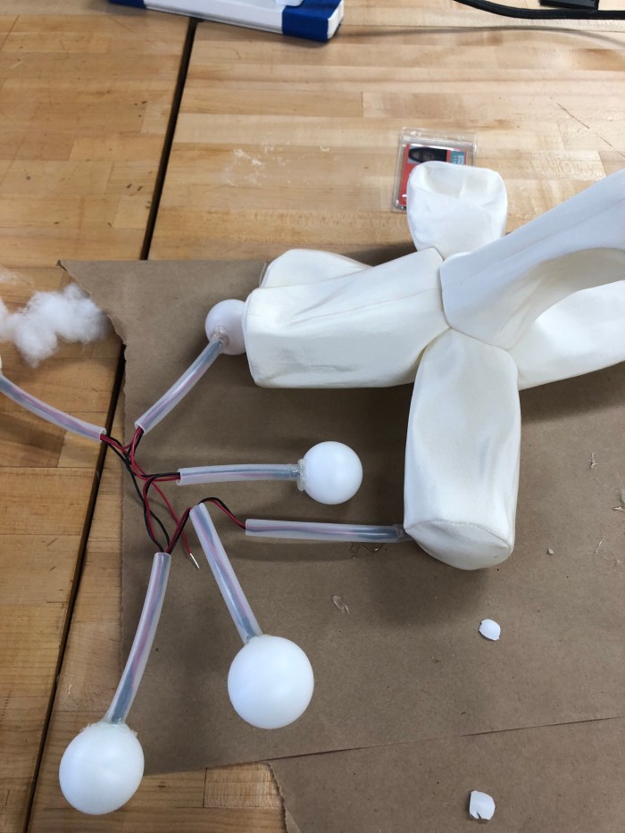
Almost all of the ping pong balls have been glued to the circuit

I also inserted a wooden dowel in each pair of spokes for added rigidity.

IMG_5851

After inserting the fiberfill, I tested the circuit for the 1345th time before soldering the battery pack and closing up the hole.

IMG_1336
Double checking the circuit before soldering the battery pack to the circuit

IMG_4628Finally closing up the plushie!

I had so much fun with this project!  Although I had given myself a difficult pattern challenge, it felt great to discover resources like Pepakura and the 3D model function on Tinkercad.  I look forward to creating more complex circuits next time.

Week 3 – Arduino Exercises

This week, we explored further with the Arduino.   The videos for the exercises are below:

      1. Digital Input

  1. 2. The Serial Monitor
  2.  For the final exercise, I decided to create a circuit and code that enables two buttons to control one LED, on and off.  Here’s the video:

I was really pleased to get this to work, as it was the first time in a while that I’ve had to figure out any code.  The code is below:

 const int buttonPinOn = 2;   
const int buttonPinOff = 4;
const int ledPin =  13;      

int buttonState1 = 0;      
int buttonState2=0;

void setup() {
  pinMode(ledPin, OUTPUT);
  pinMode(buttonPinOn, INPUT_PULLUP);
  pinMode(buttonPinOff, INPUT_PULLUP);
}

void loop() {
  buttonState1 = digitalRead(buttonPinOn);
  buttonState2 = digitalRead(buttonPinOff);
 
  if (buttonState1 == LOW) {
    digitalWrite(ledPin, LOW);
  } else 
  if (buttonState2==LOW) 
  {
    digitalWrite(ledPin, HIGH);
  } 
  }