Winnie’s Car ~ Tear down (By Qi)

Here’s the thing I found~~~ a toy of Winnie the Pooh. Though it looks ugly it can do many things as the video shows: shining lights, singing awful songs and escaping away from the shots. So!! I can’t wait to tear it down!!!!

p1

I pulled Winnie off his car.

p2p2-1p2-2


4 led lights and their control element.

p3

The switch of the toy.

p4

p5

Speaker

p6 p7

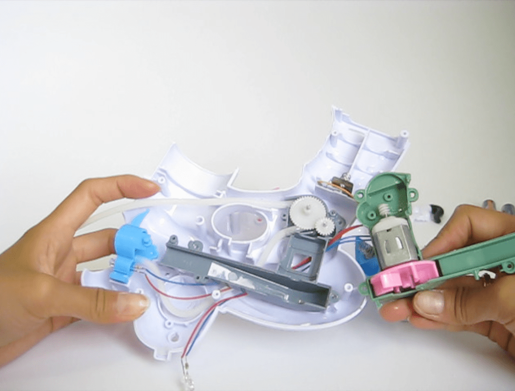
Mini motor and its transmission system.

P8

Main board.

p9

p10 p11

Lou’s DigiBird

I disassembled a beautiful singing digibird with a simple screwdriver. The bird was divided in 5: The head, the wings, the legs and the body (which was divided in two).

The 3 LR44 batteries were hiding between the legs and the body and all the rest was hiding in the body: 5 plastic connectors that each connected to specific electronic parts, a 3 part toggle switch, a speaker, a coil of thin copper wire that was connected to the head, 4 wires, a battery terminal, a capacitor, a circuit board, 4 magnets and 10 screws.

Processed with VSCOcam with c1 preset
Processed with VSCOcam with c1 presetProcessed with VSCOcam with c1 preset
Processed with VSCOcam with c1 preset
  Processed with VSCOcam with c1 preset

Movin’ Rumbler

I disassembled a toy truck which can move around and make sounds with some lights on wheels.

fotoğraf 1

fotoğraf 2

When I took out the visible screws at the bottom of the truck, the toy was divided into two pieces. The bottom part was containing all the electronical parts. The upper part was a set of some injection molded plastic peces.

fotoğraf 3

The electronical parts was containing of two cips, 4 LEDs on wheels, one motor, some plastic gears , a speaker, a switch, 3 AA battery and the battery case.

fotoğraf 5

The speaker.

fotoğraf 9fotoğraf 12

The LEDs were placed inside the wheels.

fotoğraf 17

The motor and the plastic gears. It was full of oil so I did not play much with it .

fotoğraf 16fotoğraf 8

There were two chips. The biggest one has a code (HYOOO3B) but I couldn’t find anything on Google. Also there wasn’t any code on the smaller one.

fotoğraf 21

The battery case.

fotoğraf 22

Here is the all parts. I used a single screwdriwer to tear down the toy.

Tear Down: Musical Instrument Toy

This plastic electronic keyboard toy was manufactured in China. It creates distinct sounds corresponding the pressed keys. Simple construction made it easier to dissemble. The toy also has very few components and I have indicated each ones in the video above.

keyboard-01

As I investigate each elements, I found that one of the most interesting part is the keyboards. Eight individual pieces are made of injection moulded plastic (?) and have build-in conductors underneath. When pressing these conductors, they touch the circuit board and complete the electrical circuit which create individual sounds. I believe that the designer has to truly understand the electric circuit operation to be able to come up with this solution to sound making.


all-02

Sword Tear Down by Eden Lew

[Images have been fixed]

On my way to Toys R Us, I found a Chinese toy wholesale shop. It was cheap-toy heaven. Long story short: I never made it to Toys R Us and got this rad sword for $5.

DSC_0314_small

It lights up and has 3 rotations of slashing and fighting noises.

Time to tear!

First I had to use a tiny screwdriver. Thankfully I had one lying around.

DSC_0315_small

DSC_0320_small

I had to remove 10 tiny screws before I could open the plastic “handle case.” Then I popped open the case and pulled out 3 batteries. They are T&E brand batteries, made in China, and contain 0.00% Hg (Probably stands for mercury?) according to the packaging.

DSC_0325small

After that, everything easily fell out. Unfortunately, nothing was labeled very well, so I took a guess at all the parts. First, there was a green electronic looking chip. I’m thinking this is the motherboard or brains of the toy because all the wires are soldered to it. A string of 4 clear LEDs, two larger clear LEDs, and a blue push button/toggle switch connects to the left side of the chip. The right side has connections to a circular sound speaker with the label “TWM .023 Ohms”, and two metal parts of the battery holder. I’m thinking that the push button (when pushed) sends power to the chip which sets off both the LEDs and the speaker. I do not believe that the lights and sound correlate.

DSC_0360_small

I also pulled out two plastic bulbs that held the larger LEDs. Although I don’t have a background in manufacturing methods, I can tell that these bulbs were made in halves and then stuck together like a puzzle. The exterior is a smooth and spherical-like, while the interior has geometric facets.

DSC_0355_small

To create the colored lights, 4 colored straws were taped together and shoved into a hollow plastic blade. I’m not sure why they decided to use straws instead of colored LEDs. I could tell that these straws were hand-taped, which led me to wonder about the working conditions in this factory.

DSC_0336_small

I decided to dissect the plastic, hollow blade by running my OLFA knife along the seam of the plastic. This blade was probably stamped or vacuum formed in two parts and then seals together with heat to make a hollow interior.

DSC_0344_small

DSC_0350

The two design elements that intrigued me the most would have to be in the details. I was not impressed by the designer’s solution of cramming all the electronic parts into a shell. Although it may be clever, I’m not a fan of cheap straws taped together to make long rows of colored lights. My interest is in the small details that they decided to create in such a cheap toy. The light bulb’s interior faceting is an elegant little touch that turns a regular light into a fake crystal. The designs pressed into the blade didn’t need to exist, but it adds a level of decoration to this cheap wholesale toy. These details make me feel like some thought was put into the making of this sword.

Eden

Tim & The Truck Teardown

3X7A8017 3X7A8021

This is Tim & his Truck. He deliveries packages and makes friends along the way. He also romanticizes what it’s like to be a truck driver, brainwashing little kids with adorable rhymes & melodies until they beg their parents to enter his profession.

3X7A8066 3X7A8098

3X7A8125 3X7A8151

The teardown was done using one tool: a Philips screwdriver (I couldn’t identify what size it was but it’s pretty small).

3X7A8161 3X7A8207 3X7A8213

It was rather easy to take apart and had a very simple construction. All the parts were made of plastic and were kept together by metal screws. I imagine that the parts were made by injection molding.

3X7A8221

3X7A8222

I had some trouble identifying the different chips and what they did. I tried to look them up but didn’t have much luck with my searches (someone help?). I can tell you that they operate by switch (by pushing a button) and when turned on, make a sound and also light up.

The 2 design elements that interested me were the choice to give the toy a boy dominant gender and the decision to fuse the larger chip board to the base of the toy which holds the wheels and batteries. I think the designer decided to give the toy a boy gender to appeal to wider societal beliefs of who a truck driver is and what the role represents (gender roles is a bit of a black hole so I won’t get too far into it here, but happy to talk more if you like!). For the decision to fuse the larger chip board to the base of the toy, I think this may have to do with safety and also providing a stable base for the “brain” of the toy.

Playstation DualShock 1 Controller Deconstruction

I had an old PSOne controller lying around that I thought would be perfect for this project. I used precision screwdrivers, a hammer and a larger flathead screwdriver to disassemble [and mangle] the controller:

P1030550

Here is what the controller looked like before I started taking it apart.

P1030513

As you can see, the controller is held together with seven screws. The middle screw was being stubborn, but was put into its place using a handheld electric drill.

P1030515

This is the controller opened up:

P1030516

The back case came off cleanly, taking the L2 and R2 buttons with it. The majority of the electronics within the controller were left attached to the front of the controller.

P1030518P1030520

The shoulder buttons were held on a plastic cradle. The cradle straddled a rubber mat with raised dimples that mapped onto two buttons on a printed circuit board. All of the printed circuit boards [PCB] on the controller were stamped with the numbers S003 94HB. From my research, 94HB corresponds to the part number for an LED, one of which was used for the on/off indicator for the analog sticks in the controller. I couldn’t find anything for S003.

P1030522

Below, you can see the PCB that mapped to the directional pad, analog, start and select buttons, as well as the triangle, square, cross and circle buttons on the controller. These were connected to the PCB that housed the analog sticks with a Sumitomo G91 AWM 2896 80C 16pin ribbon cable.

P1030524

Once the PCBs were removed, the dimpled rubber pads for the buttons were visible. The analog button was different from the rest in that it mapped to the PCB using a rigid plastic piece that also housed the stubborn screw that I mentioned earlier.

P1030526 P1030527

I thought that the button design for the triangle, square, cross and circle buttons on the controller was pretty awesome. Each button is keyed uniquely so that it sits flush with the housing only when it’s inserted in the correct position with the correct orientation.

P1030529

The analog stick covers were easily removed to show the following set-up. I tried to pry these off of the PCB that housed them but only succeeded in snapping the PCB in two. I tried to hammer/lever these open, but these things are very sturdily built. They are probably really strongly welded together? Makes sense, and is an example of the thoughtful design that went into the design of these controllers, as they receive a ton of punishment from hardcore gamers.

From HowStuffWorks.com, the analog stick system consists of two potentiometers at right angles to one another. Current flows through each one, but the amount is determined by the resistance of the set-up [my research indicates that the controller receives 5V from the system]. The position of the joysticks impacts the amount of resistance in the system, which can then be used to map the precise location of the joystick, enabling user control.

P1030531

The rumble functionality looks to be powered by two simple DC motors, each attached to two unbalanced weights.

P1030539P1030537

The PCB that housed the analog sticks had this CXD8771Q T5V17 9949HAL 754327 chip on it. I tried to google it, but found nothing.

P1030544

The controller’s cable head [where it inserts into the system] also proved difficult to open up. It houses 9 pins, each of which can be used to send data between the controller and the system. Here is the mapping, again from HowStuffWorks.com:

  1. DATA – This pin carries the signal that the controller sends to the PSX each time a button is pressed. It is an 8-bit serial transmission.
  2. COMMAND – This pin is used by the PSX to send information to the controller. Such information might trigger the motors in a Dual Shock controller at the proper moment. It also uses an 8-bit serial transmission.
  3. Not used
  4. GROUND
  5. POWER – This pin supplies 5 volts to the controller from the PSX.
  6. SELECT – This pin is used by the PSX to notify the controller of incoming data.
  7. CLOCK – This pin carries a synchronizing signal sent from the PSX to the controller.
  8. Not used
  9. ACKNOWLEDGE – This pin sends a signal to the PSX from the controller after each command that is received on Pin 2.

I was not able to find out what the metal [non-ferrous] collar around the controller cable did. My guess is that it regulates voltage/current somehow.

P1030546

Finally, the fully deconstructed/exploded view of the controller. The controller’s plastic casings and buttons were injection molded, as were the rubber stoppers that sat between the buttons and the circuit board:

P1030549

Bubble Gun Teardown! by Natsuki Hayashi

bubble gun_side bubble gun_bottom bubble gun_front backbubble gun_on

$5 bubble gun sold on the street corners comes with two bottles of  bubble solution and three AA batteries (inside the gun).  Only thing you need to do is to open the bubble solution cap and twist on the gun.  Two blue LED lights will light up and the pooch will blow bubbles out his mouth when you full the trigger.

Tools

I used a eye glass screw driver and a precision screw driver to remove screws, and a surgical forceps to somehow hold one part and remove other parts near the motor. And of course paper towel. I thought the inside design will be water proof, but the bubble solution was leaking everywhere and making some parts of the wire were rusted.  (Cheap toys!)

bubble gun_process_1IMG_3409

As soon as I unscrewed the bottom cover, the batteries just popped out and revealed the cords inside. The red one is connecting the batteries to the motor,  the yellow one is connecting the batteries to the trigger and then to the motor and  the blue one is attached to a resistor to the LED light and then circle back to the motor through the red cable.

I found the pink funnel with a small metal attached to the end pretty clever. It catches the extra solution dripped from the frame and channels the solution back to the bottle, and that keeps the motor and other parts from the liquid.

IMG_3412

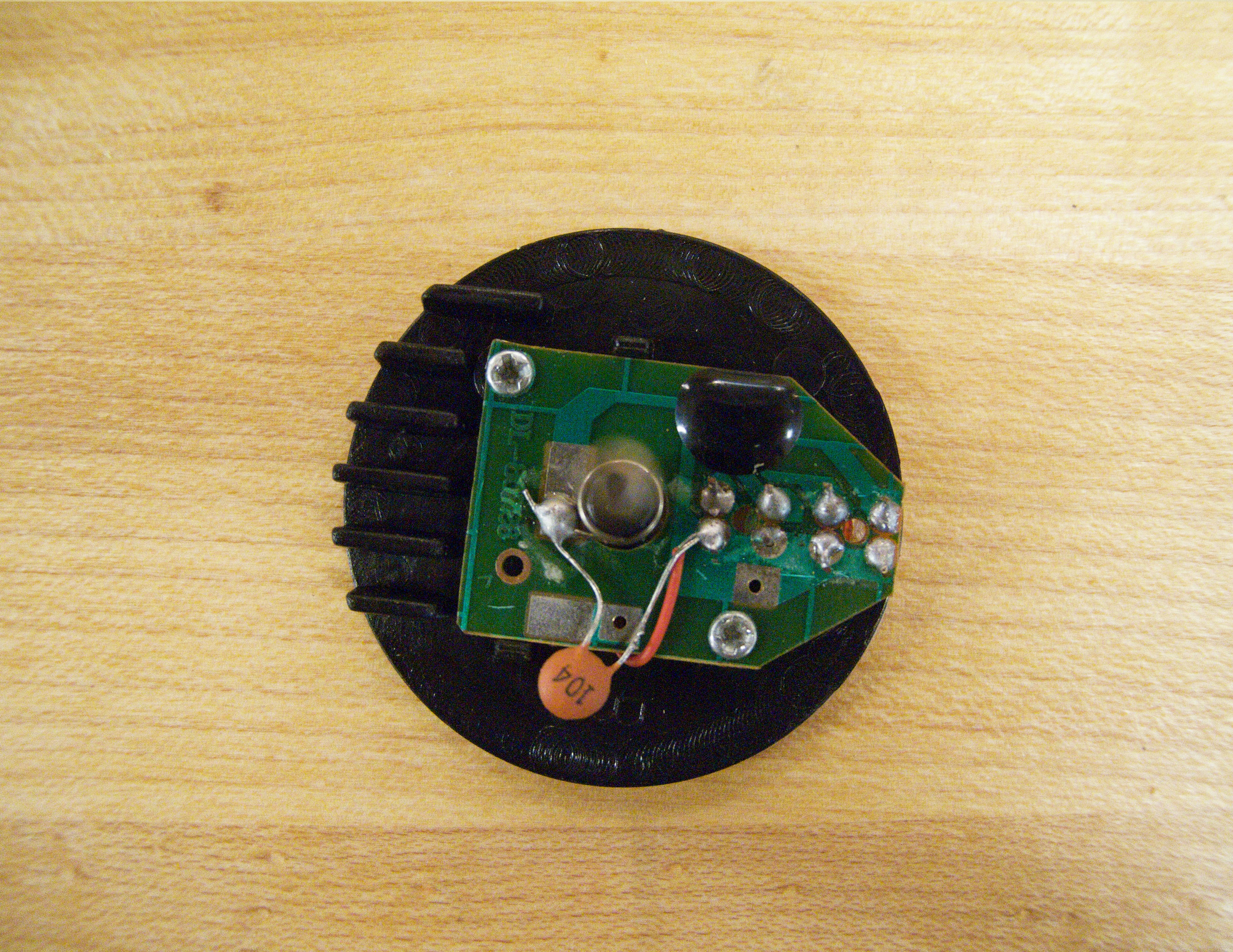
The motor is a CHAOLI brand (a chinese motor manufacture company based in Guangdong), and it  has a 104 resister (should be 100kΩ) attached to it. The welding wasn’t nicely done, so the wires were all half broken and rusted.

bubble gun_process_4

The whole system was simple yet quite complicated… the rubber hose has to suck up the bubble solution from the bottle to the frame, and a piece of blue plastic has to go up and down to make sure there is always a layer of solution on the frame. And then the pink plastic fan attached to the bottom of the motor has to rotate to blow the bubble out. Most of the parts are plastic most likely through the injection molding.

bubble gun_parts

Some parts were very loosely attached that when I removed a piece off, other pieces fell a part all together… But I found the color coding different plastic and wire parts useful, especially in assembly. There is no need to make the inside parts different color, but the designer clearly made the decision to do it for people who assemble them. Also, there was almost no glue involved in assemble the gun. Everything comes a part and designed to fit back together, so it was easy to separate the plastic and metal.

IMG_3406IMG_3404IMG_3405

I just felt like I need to share this part with everyone.  The battery cover is “Made in PRC” (meaning made in People’s Republic of China), on the cover, it says “Make In Shantou, China” and on the bottle, it says “MADE IN CHINA.”  Which tells me that they probably came from different factories in China.  The funny thing is… “Make in Shantou, China” supposed to be “Made in Shantou, China”… and “THIS NO FOR DRINKING” on the bottle is grammatically wrong yet gets the meaning across.