As a devoted enthusiast of pixel games, I’ve long relished the immersive experiences they offer on mobile screens. However, the absence of tangible warmth and physicality prompted a unique idea — to bring the pixelated magic into the real world. Thus, my venture begins: crafting my personalized pixel game, where the once two-dimensional adventures materialize into palpable, real-life experiences. This project seeks to blur the lines between the digital and physical realms, transforming every tap and pixel into a tangible, sensorial delight. Join me on this quest to turn pixelated dreams into a reality, where gaming transcends screens to become an immersive journey in the tangible world.
GAME BALL has game functions and can control lights, making it a part of home decoration. This versatility makes the GAME BALL an efficient device in any room while also adding a stylish and modern touch to the home. Whether in the living room, bedroom, or kitchen, GAME BALL can be a good decoration, making the whole room more comfortable and warm.
Main Loop: Continuously check the state of the button. If the button is pressed: Rotate the servo motor to 90 degrees. Measure the distance using the ultrasonic sensor. Output the distance to the Serial monitor. If the distance is less than 20 cm: Activate the DC motor. Illuminate the NeoPixel LED strip with a yellow color. If the distance is greater than or equal to 20 cm: Deactivate the DC motor. Turn off the NeoPixel LED strip Distance Measurement Function: Implement the measure distance function to measure the distance using the ultrasonic sensor. This code creates an interactive system where pressing a button initiates actions based on the measured distance using an ultrasonic sensor. The servo motor controls physical movement, the DC motor reacts to proximity, and the NeoPixel LED strip provides visual feedback.
Q: DC motor not working
Attempt 2:
I try to control the movement of two servos (servo motors) using two buttons, while also detecting distance through an ultrasonic sensor and controlling the state of a NeoPixel LED strip. Here’s a textual description of the code:
Import the Servo and Adafruit_NeoPixel libraries and define various pins and constants.
Set up two Servo objects (and) and one Adafruit_NeoPixel object (strip).
In the setup function, initialize the program by setting the modes for the button, ultrasonic sensor, and NeoPixel pins, as well as initializing the Servo and NeoPixel objects.
In the loop function, first check the state of the buttons.
If a button is pressed, rotate servoButton to 45 degrees, delay for 500 milliseconds, and then return it to the original position.
Simultaneously, use a loop to rotate the servoUltrasonic from 90 degrees to 180 degrees and then back from 180 degrees to 90 degrees, finally returning it to the 90-degree position.
Measure the distance with the ultrasonic sensor; if the distance is less than 20 centimeters, illuminate the NeoPixel LED strip. Additionally, use a loop to rotate the servoUltrasonic from 0 degrees to 180 degrees and then back from 180 degrees to 0 degrees, finally returning it to the 90-degree position.
If the distance is not less than 20 centimeters, turn off the NeoPixel LED strip and return servoUltrasonic to the 90-degree position.After each loop, wait for 1 second before starting the next iteration.
Q; Connecting two servo motor buttons at the same time cannot make one of them work.
Attempt 3:
Main Loop:
In the loop() function, handles the logic for the button and ultrasonic sensor by calling buttonLoop() and ultrasonicLoop().
Button Operation:
In the buttonLoop() function, checks the button state. If the button is pressed, it sets the servo angle for the button to 45 degrees.
Ultrasonic Operation:
In the ultrasonicLoop() function, uses the measureDistance() function to obtain the ultrasonic sensor’s distance reading.
Based on the distance, controls the color of the Neopixel LED strip. If the distance is less than 20cm, the LED strip is set to yellow.
Simultaneously, sweeps the ultrasonic sensor by moving its servo to create a scanning motion.
When the distance is greater than or equal to 20cm, the LED strip turns off, and the ultrasonic sensor’s servo returns to the initial position.
Ultrasonic Ranging:
The measureDistance() function triggers the ultrasonic sensor, measures the duration of the echo pulse, and converts it to a distance value, implementing ultrasonic ranging.
Q; Connecting two servo motor buttons at the same time cannot make one of them work.
An ultrasonic sensor will record the activities and upload them to your phone.
If the user interacts less than 10 times, they will receive a warning message.
Concept 2: Desk game
Use the phone to control the soccer ball.
Concept 3: Kick this button
Record the laptop or the phone’s click times and send them to Ax. Ax will “kill” the control button.
11.14 Process
Javascript game combine with physical game
Create a mobile game:
Choose a Game Development Platform:
Select a game development platform that suits your skill level and requirements. For example, Unity is a popular and powerful game development engine that supports cross-platform development.
Learn Game Development Basics:
Acquire knowledge about basic concepts such as game design, scene creation, and character control.
Create Game Scene:
Utilize game development tools to create a simple game scene and implement functionalities for controlling the character.
Design User Interface (UI):
Add a virtual joystick, buttons, or other UI elements for control, which will be used for communication with the ESP8266.
Write Game Logic:
Develop game logic, including the part that involves communication with the ESP8266. Here, you’ll need to define control commands and their corresponding actions.
Export the Game:
Export the game as an application suitable for your target platform (iOS, Android, etc.).
ESP8266 Communication:
Connect ESP8266 to WiFi network:
Use the WiFi library of ESP8266 to connect it to a WiFi network. You will need to provide the WiFi SSID and password.
Create WebSocket Server:
Utilize the WebSocket library of ESP8266 to create a WebSocket server that listens for control signals from the mobile game.
Write Code to Handle Control Signals:
Write code on ESP8266 to handle control signals received from the WebSocket. These signals will instruct the ESP8266 on how to move servos or perform other actions.
Communicate with Mobile Game:
In the mobile game, use a WebSocket library or other network libraries to send control signals to the WebSocket server on ESP8266.
Test:
Test the entire system, ensuring that control commands from the mobile game are correctly sent to ESP8266, and ESP8266 can accurately interpret and execute the corresponding actions.
Debug and Optimize:
If there are any delays or communication issues, debug and perform necessary optimizations.
JavaScript
ESP8266 code
const char *ssid = “WiFiSSID”; const char *password = “WiFiPassword”; const int webSocketPort = 81; const int buttonPin = 2; const int servoPin = 5;
WiFi.begin(ssid, password); while (WiFi.status() != WL_CONNECTED) { delay(1000); Serial.println(“Connecting to WiFi…”); } Serial.println(“Connected to WiFi”);
// Simple demonstration on using an input device to trigger changes on your
// NeoPixels. Wire a momentary push button to connect from ground to a
// digital IO pin. When the button is pressed it will change to a new pixel
// animation. Initial state has all pixels off -- press the button once to
// start the first animation. As written, the button does not interrupt an
// animation in-progress, it works only when idle.

#include <Adafruit_NeoPixel.h>
#ifdef __AVR__
 #include <avr/power.h> // Required for 16 MHz Adafruit Trinket
#endif

// Digital IO pin connected to the button. This will be driven with a
// pull-up resistor so the switch pulls the pin to ground momentarily.
// On a high -> low transition the button press logic will execute.
#define BUTTON_PIN   2

#define PIXEL_PIN    6  // Digital IO pin connected to the NeoPixels.

#define PIXEL_COUNT 120  // Number of NeoPixels

// Declare our NeoPixel strip object:
Adafruit_NeoPixel strip(PIXEL_COUNT, PIXEL_PIN, NEO_GRB + NEO_KHZ800);
// Argument 1 = Number of pixels in NeoPixel strip
// Argument 2 = Arduino pin number (most are valid)
// Argument 3 = Pixel type flags, add together as needed:
//   NEO_KHZ800  800 KHz bitstream (most NeoPixel products w/WS2812 LEDs)
//   NEO_KHZ400  400 KHz (classic 'v1' (not v2) FLORA pixels, WS2811 drivers)
//   NEO_GRB     Pixels are wired for GRB bitstream (most NeoPixel products)
//   NEO_RGB     Pixels are wired for RGB bitstream (v1 FLORA pixels, not v2)
//   NEO_RGBW    Pixels are wired for RGBW bitstream (NeoPixel RGBW products)

boolean oldState = HIGH;
int     mode     = 0;    // Currently-active animation mode, 0-9

void setup() {
  Serial.begin(9600);
  pinMode(BUTTON_PIN, INPUT_PULLUP);
  strip.begin(); // Initialize NeoPixel strip object (REQUIRED)
  strip.show();  // Initialize all pixels to 'off'
}

void loop() {
  // Get current button state.
  boolean newState = digitalRead(BUTTON_PIN);

  // Check if state changed from high to low (button press).
  if((newState == LOW) && (oldState == HIGH)) {
    // Short delay to debounce button.
    delay(20);
    // Check if button is still low after debounce.
    newState = digitalRead(BUTTON_PIN);
    if(newState == LOW) {      // Yes, still low
      if(++mode > 8) mode = 0; // Advance to next mode, wrap around after #8
      switch(mode) {           // Start the new animation...
        case 0:
          colorWipe(strip.Color(  0,   0,   0), 50);    // Black/off
          break;
        case 1:
          colorWipe(strip.Color(255,   0,   0), 50);    // Red
          break;
        case 2:
          colorWipe(strip.Color(  0, 255,   0), 50);    // Green
          break;
             case 3:
          colorWipe(strip.Color(  0,   0, 255), 50);    // Blue
          break;
        case 4:
          theaterChase(strip.Color(127, 127, 127), 50); // White
          break;
        case 5:
          theaterChase(strip.Color(127,   0,   0), 50); // Red
          break;
        case 6:
          theaterChase(strip.Color(  0,   0, 127), 50); // Blue
          break;
        case 7:
          rainbow(10);
          break;
        case 8:
          theaterChaseRainbow(50);
          break;

      }
    }
  }

  // Set the last-read button state to the old state.
  oldState = newState;
}

// Fill strip pixels one after another with a color. Strip is NOT cleared
// first; anything there will be covered pixel by pixel. Pass in color
// (as a single 'packed' 32-bit value, which you can get by calling
// strip.Color(red, green, blue) as shown in the loop() function above),
// and a delay time (in milliseconds) between pixels.
void colorWipe(uint32_t color, int wait) {
  for(int i=0; i<strip.numPixels(); i++) { // For each pixel in strip...
    strip.setPixelColor(i, color);         //  Set pixel's color (in RAM)
    strip.show();                          //  Update strip to match
    delay(wait);                           //  Pause for a moment
  }
}

// Theater-marquee-style chasing lights. Pass in a color (32-bit value,
// a la strip.Color(r,g,b) as mentioned above), and a delay time (in ms)
// between frames.
void theaterChase(uint32_t color, int wait) {
  for(int a=0; a<10; a++) {  // Repeat 10 times...
    for(int b=0; b<3; b++) { //  'b' counts from 0 to 2...
      strip.clear();         //   Set all pixels in RAM to 0 (off)
      // 'c' counts up from 'b' to end of strip in steps of 3...
      for(int c=b; c<strip.numPixels(); c += 3) {
        strip.setPixelColor(c, color); // Set pixel 'c' to value 'color'
      }
      strip.show(); // Update strip with new contents
      delay(wait);  // Pause for a moment
    }
  }
}

// Rainbow cycle along whole strip. Pass delay time (in ms) between frames.
void rainbow(int wait) {
  // Hue of first pixel runs 3 complete loops through the color wheel.
  // Color wheel has a range of 65536 but it's OK if we roll over, so
  // just count from 0 to 3*65536. Adding 256 to firstPixelHue each time
  // means we'll make 3*65536/256 = 768 passes through this outer loop:
  for(long firstPixelHue = 0; firstPixelHue < 3*65536; firstPixelHue += 256) {
    for(int i=0; i<strip.numPixels(); i++) { // For each pixel in strip...
      // Offset pixel hue by an amount to make one full revolution of the
      // color wheel (range of 65536) along the length of the strip
      // (strip.numPixels() steps):
      int pixelHue = firstPixelHue + (i * 65536L / strip.numPixels());
      // strip.ColorHSV() can take 1 or 3 arguments: a hue (0 to 65535) or
      // optionally add saturation and value (brightness) (each 0 to 255).
      // Here we're using just the single-argument hue variant. The result
      // is passed through strip.gamma32() to provide 'truer' colors
      // before assigning to each pixel:
      strip.setPixelColor(i, strip.gamma32(strip.ColorHSV(pixelHue)));
    }
    strip.show(); // Update strip with new contents
    delay(wait);  // Pause for a moment
  }
}

// Rainbow-enhanced theater marquee. Pass delay time (in ms) between frames.
void theaterChaseRainbow(int wait) {
  int firstPixelHue = 0;     // First pixel starts at red (hue 0)
  for(int a=0; a<30; a++) {  // Repeat 30 times...
    for(int b=0; b<3; b++) { //  'b' counts from 0 to 2...
      strip.clear();         //   Set all pixels in RAM to 0 (off)
      // 'c' counts up from 'b' to end of strip in increments of 3...
      for(int c=b; c<strip.numPixels(); c += 3) {
        // hue of pixel 'c' is offset by an amount to make one full
        // revolution of the color wheel (range 65536) along the length
        // of the strip (strip.numPixels() steps):
        int      hue   = firstPixelHue + c * 65536L / strip.numPixels();
        uint32_t color = strip.gamma32(strip.ColorHSV(hue)); // hue -> RGB
        strip.setPixelColor(c, color); // Set pixel 'c' to value 'color'
      }
      strip.show();                // Update strip with new contents
      delay(wait);                 // Pause for a moment
      firstPixelHue += 65536 / 90; // One cycle of color wheel over 90 frames
    }
  }
}
My toy is called Madmad, and it serves two purposes: helping adults overcome sleep difficulties and assisting individuals in relieving stress.
As children, many of us find comfort in holding onto something to fall asleep. This habit often continues into adulthood. Madmad is designed to cater to this need. Inside, I’ve placed plastic and paper, so when it’s squeezed, it produces a soothing noise that helps people release their stress.
Madmad is divided into three parts: the eyes, the body, and a button. The toy is designed to enclose a ball within it, featuring LED lights, buttons, and soft cotton material. When the button is pressed, Madmad’s ears light up, creating a calming atmosphere.
This versatile toy can be placed on bedside tables, in office rooms, or taken along while traveling. I’ve added a convenient button, making it easy for people to carry it anywhere they go.
The head wires incorporate LEDs and buttons. As you approach the toy, the LED lights will open.
My brand is Madmad, and our primary mission is to assist individuals in relieving stress.
Madmad offers a unique stress-relief toy, which is divided into three parts: the head wires, the body, and the backhand.
The toy is designed to house a ball within it, containing both a pressure sensor and cotton material. When the ball is pushed, it triggers changes in the LED lights on the head wires.
The head wires incorporate LEDs and distance sensors. As you approach the toy, the LED lights will flash, providing an engaging and interactive experience.
Apple iPod photo classic 4th Generation White (20 GB)
YHYZ Precision Tweezer ESD-12
JRready ACT WN10 Wire Cutters Precision Flush Pliers 5 inch Precision Extensions for Hand Tool
Uxcell Non-magnetic Curved Tip Tweezer Anti-static Stainless Steel Precision Multifunctional
Economic long Round Nose Pliers
Chrome Screw Driver
Use the Wire Cutter to pry up against the plastic front panel and release five retaining tabs
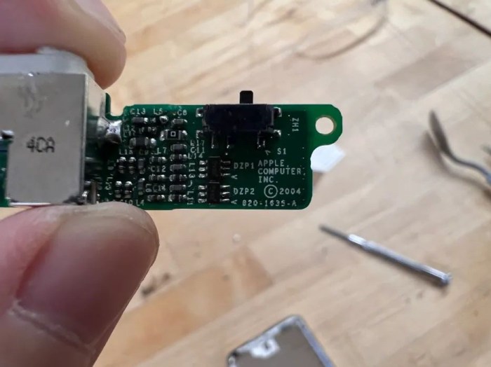
Headphone Jack and Hold Switch(820-1635-A)
Standard 3.5mm headphone jack. The material used for the headphone jack was typically metal, which provided durability and good electrical conductivity.
Hold Switch
Headphone Jack & Hold Switch Flex Cable(632-0260)
Flat Ribbon Cable: flat ribbon cable, which consists of multiple thin conductive wires sandwiched between layers of insulating material. The insulating material is made of a flexible plastic.
Connectors: At each end of the flex cable, there were connectors or plugs made of plastic or metal. These connectors allowed for the cable to be connected to the headphone jack and hold switch on one end and the main logic board on the other end.
Insulation: The cable also had insulating material to protect the conductive wires and prevent short circuits. This insulation was made of a flexible, durable plastic.
Hold button (plastic)
Plastic: Plastic is lightweight, durable, and can be molded into various shapes and sizes.
Hold button
White Plastic Dock Bezel
Rear case (stainless steel)
Hard drive cable
TUSHIBA hard drive MK2004GAL
Toshiba MK2004GAL 20GB UDMA/100 ATA-5 4200RPM 1.8″ Inch Mini Hard Drive Hybrid (HDD/SSD)
DMA/ATA-100 (Ultra)
Toshiba 20GB 1.8-inch Mini Hard Drive General Features: 20GB formatted capacity UDMA/100 transfer ratio.
ATA-5 interface 2 MB buffer 4200 RPM spindle speed 7.14 ms average latency 15 ms average seek time.
1.8-inch form factor Low-power consumption Power Specifications: DC 3.3V 500mA Regulatory Approvals.
Logic board
Logic board and display
Apple 820-1535-A Logic Board
Fiberglass or PCB Material: The main substrate or base of the logic board is usually made of a fiberglass-reinforced epoxy laminate material, commonly referred to as a Printed Circuit Board (PCB).
Copper Traces: Conductive traces on the PCB are typically made of copper.
Solder: Solder is used to attach electronic components to the PCB. It typically contains a mixture of metals, including tin and lead.
Silicon Chips: The logic board houses various silicon chips, including the CPU (Central Processing Unit), GPU (Graphics Processing Unit), memory chips, and other integrated circuits. These chips are made from silicon.
Connectors and Ports: Connectors and ports on the logic board may be made from various materials, including plastic and metal.
LCD Display (F-51824FNF-SLM-AD)
(Looks like there’s some screen fluid leaking)
Plastic Front Cover: touch-sensitive surface for user interaction.
Liquid Crystal Layer: The core of the LCD screen is the liquid crystal layer, which is made of organic molecules that can change their orientation in response to an electric current. This layer is responsible for controlling the passage of light through the screen and creating the images and colors you see.
Backlight: LCD screens require the liquid crystal layer. The backlight is typically made up of small LEDs (Light Emitting Diodes). Include semiconductors and various types of plastics or glass for housing and diffusion.
Thin-Film Transistors (TFTs): TFTs are used to control the individual pixels on the LCD screen. (semiconductor materials, such as silicon)
Color Filters: To produce full-color displays, color filters are used in LCD screens.
LCD Display back
White Front Faceplate
Covered the front of the device and housed the screen, Click Wheel for navigation, and other controls.
Battery(616-0198)
Lithium-Ion Cells: The core of the Li-ion battery is the lithium-ion cell.
Anode (Negative Electrode): The anode in a Li-ion battery is made of carbon or graphite materials.
Cathode (Positive Electrode): The cathode is made of a lithium-based material, such as lithium cobalt oxide (LiCoO2) or other variations.
Electrolyte: The electrolyte is a crucial component that allows lithium ions to move between the anode and cathode during charge and discharge.
Separator: A separator is used to keep the anode and cathode from coming into direct. The separator is a porous material, such as a polymer.
Protection Circuit: Many replacement Li-ion batteries, especially for consumer electronics like iPods, include a protection circuit board (PCB).
Connectors: The battery often includes connectors for easy installation and connection to the device.
Front panel
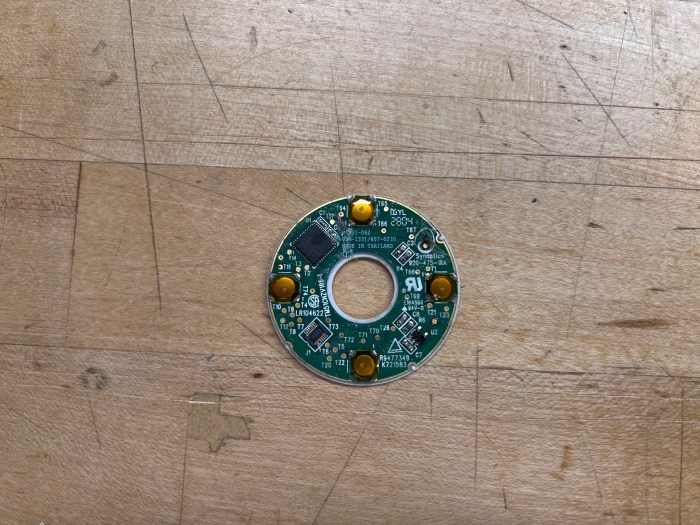
Click wheel(657-0230)
The click wheel operates by sensing user input through its touch-sensitive ring, which can execute multiple commands thanks to four mechanical buttons positioned beneath it.
The primary technology at play in the click wheel is capacitive sensing technology. When an electrical voltage is applied across two conductors situated closely but not in direct contact, it results in the storage of energy in the form of an electric field. Even after the voltage is removed, the stored charge remains, illustrating how capacitors gather and retain energy.
In the case of the click wheel, this property of capacitors is harnessed to detect the position of the user’s finger due to the capacitance between the human body and the conductive film beneath the plastic cover of the click wheel.
Flex Cable( Foxconn 2604)
Connect the click wheel and logic board
Design elements that interest:
Click Wheel: I appreciate the Click Wheel’s efficient scrolling and tactile feedback, which even includes a satisfying sound when pressed. It allows me to swiftly locate and choose what I want without the need for excessive button presses. When I try other music players for the first time, I often find that clicking their buttons can be uncomfortable and strain my fingers.
iPod switch button:The switch button is a feature I frequently utilize on all Apple devices, although it functions differently on iPods compared to iPhones or iPads. iPods are more prone to accidental touches, but the switch button effectively addresses this issue. It simplifies the process of locking the screen and the wheel. Whether I place it in my pocket or any other location, it doesn’t negatively impact my user experience.