Hello,
I think I found one of the typos Becky challenged us to find, page 11 on the Experimenter’s Guide:

Am I correct? is everyone gonna hate me now? =)
Hello,
I think I found one of the typos Becky challenged us to find, page 11 on the Experimenter’s Guide:
Am I correct? is everyone gonna hate me now? =)
Thought you folks might like this recent iPhone 7 Teardown by iFixit.

The whole body is made of plastic and the keyboard is made of rubber, the main assembling way is using screws, and some of the parts locked together,the most interesting part is the ball in the center of four keys,it will hit on a button which on the circuit board when you push it, but there’s no reaction when you roll it. The reason why designer do this is because the press button is pretty common on children’s toys, but rolling ball button is not common and kids can explore the feeling of rolling and pressing at the same time.the rubber keys give you a good touching feelings. and one more interesting parts is the rubber keys, they touched more soft than the side key and light keys, kids can get different feelings when they tough the keys on the toy. the light keys are made of PVC plastic, the other parts I’m not sure. but design for kids should be safe.
#chrisRand
This macMini was bound for the e-waste collection but first made a pit stop at my workbench so that I investigative and tear it down. My intent was to learn about how this compact computer was engineered, how dissimilar materials are used, how are parts joined together.

The first place to begin is to locate the main chassis screws that hold the shell together. Normally, the screws would be directly visible in the back of the device or concealed under some kind of rubber bumper or pad on the bottom. I peeled back the bottom pad and found nothing ! Was this going to be a tedious process like solving a master-level puzzle ?

Knolling : the top surface and side chassis. Galvanized steel sheet has been laser cut or stamped and then brake-formed for the top and bottom panels of the macMini. The steel serves 3 major functions; to strengthen the injection molded plastic panels, to create clips for fastening the sub-assembly to the aluminum chassis, and an integrated safety switch. If the plastic top panel is removed for repair or service, the neutral path of electricity is interrupted and prevents the unit from powering up.
I wanted this to be a non-destructive process as if I was a repair technician and i quickly learned that. . . . . YES ! this IS a masterful puzzle to completely disassemble. The example below is from the disc drive mechanism that pull the disc in / out of the chassis.
 STEP 1 : rotate metal piece to expose the white plastic part below.
STEP 2 : slide the plastic part back and forth.
STEP 3 : notice or identify that there is an access hole only when the part is in a specific position.
STEP 4 : remove the screw that holds this component.
In addition to standard and custom mechanical fasteners, there were many cleverly concealed means of joinery like CLIPS, TABS, RIVETS, SPOT WELDS, and some that I’d call mortise and tenon. The engineers wanted to use minimal screws for aesthetics for the exterior of the MacMini but why did they use so few screws on the interior? Do screws take up more time in manufacturing and assembly or are there other ways to solve fastening?
Instead of using 4 screws to hold a part, there would be one or two used in conjunction with tabs, clips or tenons. I found that neighboring assemblies would hold one-another in place. What can we call this methodology. . . . screw sharing?
 Creating something that is brilliantly simple often requires more effort.
The injection molded ABS plastic internal chassis was engineered to serve many functions ;
• a skeletal structure that holds the hard drive, most of the PC boards, and the fan.
• integrated ducting to circulate cool air around the device.
• integrated wire conduits, wire clips, and acts as double insulator protecting electrical wires from areas of increased heat.
I was delighted to find that the DVD drive was filled with good old mechanical components used to actuate motion like springs, hinges, motors, gears, linear actuators, and worm shafts.

VIBRATION control : what a delight to discover that the audio speaker was isolated from the chassis with medium density rubber which allows the music to bump/bump and sound clear at high decibel.

PART IDENTIFICATION : Throughout the teardown, I thought about reusing some of these fascinating parts in a future Arduino project, like the LED board. In order to understand how to use it, I search ElectronicProducts.com and discovered how every part is specifically called out including the material, manufacturing process and physicality. The wire harness, mounting bracket, connector, and the black foam rubber pad (die cut w/PSA) are all specified. Below is how just the PCB assembly was called out;

SUMMARY : similar to reverse engineering by way of a 3-dimensional schematic, this was an exciting and fascinating activity. I realized that heat must be a major factor in the considerations of designing a compact and powerful computer evident by the insulators, sinks and the distribution and air circulation. There were far more mechanical systems than expected in a digital machine and if the CD drive were to disappear, it would eliminate two motors, about four assemblies composed of up to 28 parts and save on space and the use of lithium grease for lubricating the plastic gears and slides, totaling over a hundred pieces. The MacMini was made to be repaired with exception to a few blind rivets used in the hard drive’s axis and the individual components soldered to the PC boards.
The disassembled MacMini quickly laid out.

Further research may include;
• electromagnetic interference EMI that is created by the device / how the MacMini was designed to shield from the EMI of other components such as a wireless keyboard and monitor.
• identifying the manufacturing processes used, including assembly and disassembly.
• creating a resource, use and waste list to understand the life cycle of this product.
• part list : calling out the size, material, manufacturer and function of each part.
• composing a step-by-step guide to disassemble and reassemble this device.
Cheers !
Chris Rand
I found this video insightful and relevant!
This simple toy is my subject to teardown. Powered by AAA batteries it involves a rotatory motion and lit LEDs when a button is pushed.
The initial unscrewing yields the inside of the toy.

Taking out the useful part from the casing shows a button, 5 LEDs,small circuitry,a motor and connecting wires.
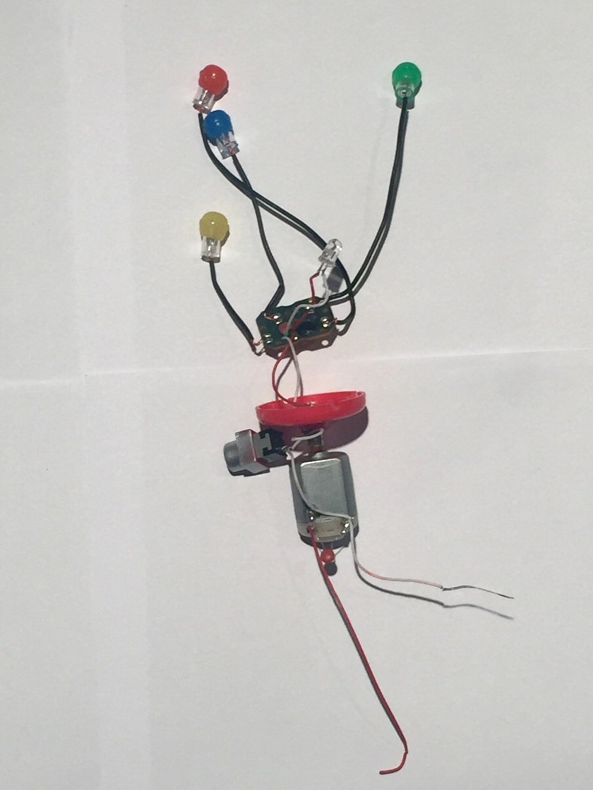
Exploring each section separately, the lighting component of the toy is shown. Consisting of 5 LEDs connected in a simple circuit.The only use of the circuit board is powering the LEDs,which are soldered to the board with wires.

The Pushbutton type switch is used to operate the toy.These switches complete the flow of electricity when they are pressed. When a pushbutton switch is in the on position, a spring inside the electrical device makes contact with wires that will allow the current to flow. Then, when the switch is pushed down again, the spring inside retracts, and this stops electrical current, deactivating the device.

For the rotary motion, the toy uses a brushed DC motor.

The final layout is shown as,

The tools used in this operation are,

UPDATE:
Part-Manufacturing Technique
Head- Making a mould and casting
Body- Making a mould and casting
LED Lights- A semiconductor wafer,multiple wafers are joined to become a semiconductor,Ultrasonic process to clean it.
Electrical components- Include highly detailed intricate processes,although very cheap to make.
The one design choice I like is the simplicity of the button placement. Very child friendly and surprisingly sturdy.

It started like this.
The small star problem: the star-shaped drills in VFL were all too large for these stars.
So I drilled through the screws… until the bit broke off.
And used a vise grip unsuccessfully… until Chris gave me his star-shaped screwdrivers. His stars were the perfect size!
The top finally came off!
Then I unscrewed everything I could get my fingers on like this piece.
and these discs.
Then, it was time for the other side. It became obvious that whoever designed this harddrive really didn’t want me to tear it open. S/He used 4 different sizes of screws to attach the circuit board to the base board.
But I did it anyway.
This side had many films. Like this one.
And this.
And this. The black board must not have wanted to touch the green one. Who can blame it? The green board is spiky and full of circuits.
Underneath all the pieces, discs and films, the black baseboard showed its very peculiar self. It had a cylinder that turned on one side, but on the other, remained still.
It looked like the cylinder was riveted in a rotating core. The lip of its rivet was sticking out of the board. So I decided to file it away to set the cylinder free.
But filing was not enough to set the cylinder free. So I drilled through the rivet (without breaking the bit this time!)
When I set the cylinder free. It showed me a piece that it had been securing inside: a ring of copper wires that looked electromagnetic.
To take this unexpected treasure off of the board, I hammered through its core, hoping that by removing the core, it would let me take the ring.
But no matter how many times I hammered, the core wouldn’t move. So I dremmeled through the whole board. 
And finally got the ring off!
Tools Used: Drill, vise grip, screw driver, file, hammer, magnifier, plier, file, drimmel
2 Design Elements: I love/hated that the designer of this hard drive used so many rivets to connect pieces vertically. The rivets in the cylindrical core was incredible; there was not even a sliver of space between each piece to let me ply it open. While they made it frustrating for me to tear everything down, the whole process made me appreciate the precision involved in manufacturing this product.
Also, there was a stark difference between between the two side of the board in terms of protection. While the side of the circuit protected it by layering multiple films between the circuit and the board, the other side prevented particles from entering the device. The rubber lining on the cover sealed it onto the board, making it impossible for dust to enter it. I was surprised that nothing similar was on the circuit side. Aren’t circuits at risk from dust also?


The Nintendo DSi was a handheld gaming console released in 2008/2009. Its logic board (C/TWL-CPU-01) carries 3 chips:

There were a number of screws that the designer had hidden behind plastic casing, so I had a bit of trouble locating them all. To complete the deconstruction, I mostly used a small bit driver, but used a knife/medium screwdriver as wedges to pull pieces of the casing apart.
This might not be much of a surprise to the experienced industrial designers, but the first design element I was interested to discover was that there are pads behind all of the buttons. For some reason I always assumed they were set on springs:

Mostly, though, I wanted to figure out the design and materials behind the making of the touchscreen. I find resistive screens particularly well designed as there is an inherent sense of user feedback to its function. However, I wasn’t expecting to find the several layers of film behind the glass:

I’m sure there are many, many more manufacturing techniques in the process of building the DSi, but the ones I’ve inferred so far are:
I still remember the excitement surrounding the release of the first of the DS line, the Nintendo DS, back in 2004. Being in high school at the time probably added to the feeling that everyone had one. At the time, the design elements that excited the people around me were the dual screens, touch screen capabilities, and if I remember correctly, the smooth integration of the stylus fitting as though it was just another part of the case.
Today, I’m interested in the designer’s decision to only to include touch for the lower screen and not the upper. Was it a question of frailty (users would push too hard and the hinges would give)? Another reason I can think of is that the designer felt users would only use the touchscreen on the lower face, as pushing down feels better than pushing at an incline.

The second design choice I’m intrigued by is the location of the camera on the central bar (on which the console flips closed). No matter how I picture it, the angle at which it would capture the user seems very awkward! I’d love to know what drove the designer to choose to place the camera there instead of at the top of the upper lid.


I walked into a thrift shop and found a Bad-ass looking space shooter.
It was pretty easy to tear down the product using bare hands and a screw driver!

Below is the description of the Part , its material and the manufacturing process.
It was fun doing this activity! Sad I couldn’t put it back, as I stripped down even the last piece of wire!
#sowmyaiyer
