I’m a maker with a background in a variety of materials including steel, wood, and ceramics. I’m originally from central Arkansas, but most recently moved to Brooklyn from a small craft school in the Blue Ridge Mountains in Western North Carolina. Experimenting with new materials and processes is one of my favorite things. I also really enjoy good food and good tea. Before a recent injury, you’d likely find me playing Ultimate when I wasn’t working, eating, or sleeping. I’m working on that and I’ll be on the field again soon!
I’ve always had running nose problems since I came to NY due to the seasons. So then I realized what if I can measure the temperature from outside with buggers. I sculpted a nose and programmed my arduino to be temperature sensitive. This is how the nose works: When the bugger is blue/ Frozen the temperature is lower than normal in the room. And when it turns the color to yellow then it’s warm again.
I grew up in a home with a lot of mirrors. Even if you’re not a vain person, if there is a mirror in front of you, it’s difficult to resist the temptation to at least glance in the mirror to check your reflection. It’s a tendency that I grew up with that I really dislike because it makes me feel superficial; on some level, I think that it actually does make me more vain, little by little. I wanted to discourage this vanity-inducing habit by creating a mirror that is only reflective for a short time before “turning off” [in its actual implementation, this time is 5 seconds].
I had read about smart film in a book by Dan Brown, and began to look for places online that would source it. It turned out to be incredibly expensive [$200 per sq. ft.], but I was able to get a small piece of 6″ x 6″ smart film that I made this mirror with. I initially thought it would be a good idea to build a frame out of 2×4 wood because I had planned on plunge routing a hole out of the wood to store my board and components in. This resulted in a pretty abysmal looking design:
I bought thinner planks of wood and settled on mounting the components of my circuit on the back of the mirror. If I bring this product to market, I’ll be using a much smaller microcontroller, so it’ll be easier to keep the controller out of sight. For the remainder of the bulky material [namely the 12-40v convertor [more on that later]], I could always laser cut a case out of acrylic to house it in.
I had to cut channels in the wood to receive alligator clips; the smart film requires a really strong connection with its power supply, otherwise it has a tendency to flicker or not turn on at all.
I had originally experimented and tried to find perforated or clear material that I could hide the sensor behind within the frame, but I couldn’t find anything. I ultimately chiseled a hole out of the wood to fit the sensor, but accidentally chipped the exterior of the wood.
I used some veneer, courtesy of Boris, to patch up the cracks:
I also spray-painted the wired connection of my IR sensor black so that it wouldn’t be uber-visible through the hole that I made.
Here are two shots of the mirror in its on and off stages:
So now that the story of the physical build of this mirror is complete, I’ll regale you with the tale of the TWO Arduino boards and 1 IR sensor that I destroyed while making this mirror. I struggled with Boris, late one Wednesday night, trying to use a transistor to turn the circuit that controls the mirror on and off. You see, the smart film requires 40V to become transparent, which is more voltage than the Arduino could safely handle. The original idea was to use a transistor to control the flow of electricity between the 12V power source and the 40V convertor, but the transistor just wasn’t working. We then tried to use a relay, but the relay wasn’t working either. We finally tried a combination of the two… and that still didn’t work [what gives?!].
We pulled out the multimeter and realized that my Arduino board was fried, probably due to a short circuit earlier in the day, and wasn’t delivering voltage to the pins. With a new board, I was able to successfully flip the relay to power the film. The only issue [which would manifest itself in disaster the next day] was that the relay was controlling power to the 40V side of the convertor, instead of the 12V side. So the next day, as I was tweaking my code, which was largely functional, the power surged [or at least I think it did], my computer turned off, and my board fried. Also, my IR sensor was completely fried. Sad beans.
I rewired the circuit, removed the transistor and only relied on the relay, which now modulated my smart film circuit on the 12V side. Interestingly, because the convertor stores current, the smart film’s once discrete transition from clear to opaque and back again became gradual; I had to alter my code for this. The only issue that remained was a debouncing problem – when I stood at the edge of the mirror’s range, the mirror flickered on and off almost continuously. The way that my code was set up originally, I was checking for a state change defined by a baseline reading in the IR sensor, and then activated the smart film based on this reading and state change.
I tried debouncing, initially by setting a timer based on when the mirror knew someone was standing in front of the mirror, but this didn’t work because the debounce timer reset continuously when I wanted it to be activated just once [i.e. I wanted the timer to run when someone was standing in front of the mirror]. Because the bouncing occurred at the edge of the sensor’s range, I realized that I could start the timer on the off position, so that it ran when someone stood in front of the mirror. The problem now was that because the code was looking for a state change, it would only ever activate the mirror right after someone stood in front of it, when it would fail the debounce time requirement. I changed the methodology for controlling the relay, so that it specifically looked for a state continuity – the code had to loop twice with the switch activated for the mirror to activate. To allow the mirror to turn off [remember, the debounce timer was running off of the off state], I added a second loop that looked for the off state specifically, and turned the mirror off.
I have been working hard on my Tide Clock. I have been making progress and throughout the process some things have changed since my original post. Initially, I planned on using a water pump and a solenoid valve to pump and drain water between the two chambers of my clock. After purchasing a water pump and experimenting with it I decided that the noise and size of the pump, in addition to a valve, were much too loud and large for what I want to achieve. The experimentation process with the pump was frustrating, but it was worth it because it lead me in the direction of water displacement!
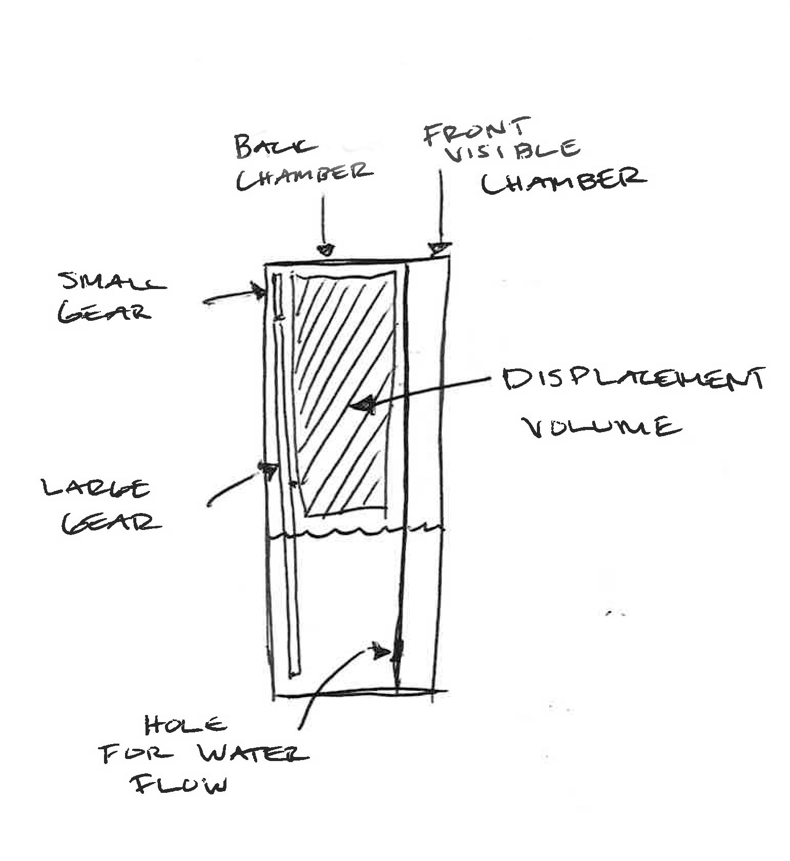
My new plan is to use a large volume to displace the water from a back hidden chamber to a front visible chamber. I made a quick prototype to test my new plan. I simply created a divide between the front and back of a container of water and lowered and lifted a volume into the back section. With very little water overall, I was able to cause the water level in the front section to rise and fall:
I then sketched out how this would work in a circular form:
I created a more detailed prototype to test out the size and shape of the volume that will be causing the displacement:
It works really well! I am going to use a stepper motor to move the volume. It will be mounted above the water line and attached to gears that turn the volume.
Here is a side view:
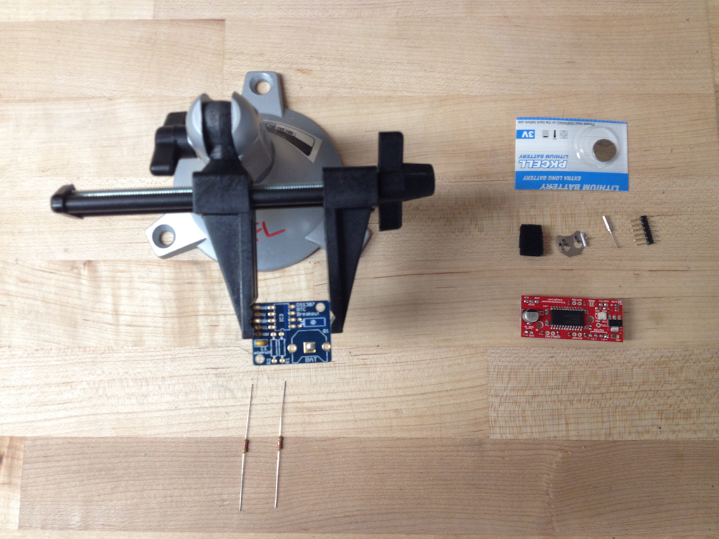
My next step is to work on the electronics. I am going to control the stepper motor using Arduino. I will calculate how many steps it takes to get through a full cycle from high to low tide. I started by assembling my Real Time Clock. I will have more detailed instructions of this in my step-by-step tutorial . Here is a preview:
I am now in the process of getting the stepper motor up and running. I have it wired it up but I haven’t successfully managed to get it running.
This is a project on using 123D Catch to get a 3D scan of my whole body. Once I had the scan I cleaned it up and manipulated it ready for 123D Make. I sliced the model in Make and preped it for Laser cutting. Once done I lazer cut and integrated the componentry and Arduino to make the head turn. I created two functions an automatic tracking function and a manually controlled function through Max MSP. In a way this is a Modern Day Puppet.
Introducing the “ijunk” – the junk mail iphone / ipod dock
“the best thing to happen to iphone since iphone 5”
When an iphone or ipod is docked it activates a junk mail delivery mechanisim. This was a really project with no apparent purpose but gave me the opportunity to use a physical imput to create a digital action in the ardino code and then return a physical output. The physical circuit uses a tip120 transistor which acts as a electronically controlled switch allowing the motor to draw power from an independent power supply. This is important as if the motor were to be connected directly to the arduino it could fry the arduino’s chip. The code i used was a version of the button example featured in the continue reading section of this post. Ideally if I had more time I would have better integrated the iPhone charging into the arduino and have it actually recognized when it was being docked, rather than just using the phones casing to connect the circuit via contacts.
Some of the tutorials and useful sites I found and used are here: