Sounds and Lights Birthday Card TEARDOWN

My dad gave me a special card for my 30th birthday. And then I tore it apart.

Tools I used 4

COMPONENTS OF BIRTHDAY CARD

What astonishes me most is the quantity of materials and features that you can get for a mere $7.99. This birthday card has 4 batteries, a small circuit board, a web of fiber optic filaments and the resulting effect of light, sound and birthday magic.

The card was fairly easy to dissect, but through its construction, it’s obvious that these materials are not meant to be repaired or reused.

inside cardAs for the manufacturing process, we can see evidence of how the elements are hand-assembled in the final stage (there are graphic marks for where to place the round battery pack & the clear plastic battery cover that activates & shuts off the animation when you open & close the card). The elements themselves are large-scale factory produced pieces: circuit boards made from a process described in-depth here; plastic parts injection-molded; the paper card from an inkjet printer. (I googled the circuit board serial number to no avail!)

Two construction choices that interested me were the way that the fiber optic filaments were individually threaded through tiny holes from within the card and popped out through the birthday message, creating the appearance of dozens of separate blinking lights.

The other is more a befuddlement than an interest: double-sided tape was used everywhere, but sometimes the backing hadn’t even been removed. Cleary the manufacturer should substitute double-stick tape for regular tape in some areas.


Ironman Teardown

Otherwise known as “the cool Ironman toy I’ll never get to use”

cover

I chose to see what was going on inside this toy I found at a thrift shop. I think it was supposed to be an Ironman sleeve, but there were no batteries inside when I got it and I think it was already partially broken, so I never saw it turned on.

first image

I only used a couple of tools to take it apart: a tiny Phillips head screwdriver, a pair of needle nose pliers, and a sharp piece of metal to pry things apart. Here is what I found inside:

open toy

final spread with labels

electronics

I managed to find all of the electrical components online, as well as most of their datasheets. I put all of the information and links in this table, including the purpose of each component!

While many of the plastic parts for this toy were injection-molded, the electronics were sourced from a variety of companies and the entire toy was likely assembled by hand. The palm light was welded closed, while the battery pack was glued (hence the broken pieces in those two circles!). The rest of the parts were assembled with six different kinds of bolts.

The two design elements that interested me most were 1) the conductive strip in the wrist hinge and 2) the fact that the palm light part of the toy is the only part that was welded shut. It took me a little bit to figure out the function of the conductive strip, but I think its purpose was to make the palm light turn on when the wearer’s wrist was bent (flexed) and off when the wearer’s wrist was straight (relaxed). With a bent wrist, the two conductive strips in the hinge would touch, closing the circuit (turning on the light), but when relaxed they would separate, opening the circuit (the light stays off). Pretty neat. As for the one welded part, I suppose it would have been a bit impractical to use bolts in that part of the toy. Perhaps it was more important to keep the Ironman aesthetic despite the required welding equipment.

For more pictures, click here.


Teardown – Remote Controlled Car

Remote Car Teardown from Antya Waegemann on Vimeo.

The car teardown was super interesting and fun. It was a little difficult at first to figure out what every was. It seems as though the materials used to make it were rather simple including the circuit board, wiring, small motors, batteries, and then the plastic to make the mold of the object.

The only tools I needed for the teardown were a small screwdriver, a larger screwdriver and then some scissors to cut the wire to separate everything, but it was rather easy to take apart and seems like a lot of glue was used as well.

Two design elements that interested me about this product was first the simplicity of it. It looks really complex especially as a remote control car, but taking it apart showed me that it really didn’t have too many components. Another design aspect that interested me was the motors and it would be interesting to see how the work and how it all connects, almost as if I could have a translucent car.

teardown2-01teardown1-01


My First Teardown

For my first-ever teardown, I disassembled, (and mildly destroyed) a Nintendo Wii remote. I only needed access to a few tools, which include a tri-winged screwdriver, a metal file (to level some of the plastic pieces), and an Olfa blade to help pry the device open.

What you’ll need:

  • tri-winged screwdriver
  • Olfa blade
  • File*

*Dependent on screwdriver

  img_3908.jpg                      img_3896.jpg

             (Left to Right: Tri-winged Screwdriver, File (Letterman Knife), Olfa blade)

First, examine the backside of the remote, and remove the battery cover, there are two small screws you will need to remove, with the tri-winged screwdriver located where each battery sits.

IMG_3898

Next, you’ll want to pry the two main pieces apart. Don’t do that just yet — you still have two screws to find. They can be found at the bottom of the remote, on the backside, under the two screws you have already removed.

*Pro Tip* make sure you have a narrow and long screwdriver to complete this task. The screws are encompassed by tall walls of plastic and are tough to get to.

I did not have the means to reach the screws initially and needed to take a detour. The photos below showcase the brilliant use of a metal file. The file was able to eat through the plastic fairly quickly and leveled the plastic, allowing me to reach the screws with my screwdriver.

This slideshow requires JavaScript.

Now, you can pry the remote into two pieces easily, like this:

IMG_3904

Look at those muscles!

IMG_3905

And here are all their names…

WIIMOTE

WIIMOTE BACK

In this particular device, all components on the circuit board are soldered.

In breaking down the components of the Wii remote, I particularly enjoyed the small rubber/ plastic bits that are placed between the external buttons (which we press) and the circut board. These pieces are a smart design decision because their flexible and soft qualities prevent any contact between buttons and the circuit board. Also, the experience of pressing a button, and the slight resistance that the soft pieces provide, is a feeling that gamers and non-gamers alike can joyfully relate to!

Similarly, the hinged plastic embedded in the back portion of the remote, used for pressing “B” with your index finger, is a smart design choice. The button is modeled after a trigger, which evokes a certain reaction during fictional play for gamers. Rather than insert a typical button, the hinge calls for a particular action from its user.


Xuan’s TEARDOWN

Hi everyone, I found a ‘music toy’ which I think is for kids, with a couple of buttons, three LEDs and a speaker.

xuanzi.jpg

Manufacture technology

The wires and chips or metal are connected by soldering. The whole manufacturing process of PBC board is:

流程.jpg

The plastic casing is made by injection molding or slush molding.

At last, assemble everything.

Part numbers

IMG_1816.jpg

I think the part number is hj-051-1c, but I have trouble with finding a match on datasheet.

Tools

screwdriver & cutter

Design elements

1.As you can see from the image down there. The keys on the outer surface of the toy can be pressed from all four directions. But the interiors work in a completely different manner. There is one button inside which, when pressed on the right side for example – connects the circuit on the right. This completion of the circuit results in a particular song being played. This essentially means that there is one conductive button inside which plays all four songs.


IMG_1820.jpg

2. Another element is switch.

222.jpg

Ummm, I really don’t know how to arrange my words shortly. The switch is very simple but a little bit tricky at the same time. If you want to know, come to me, I can explain it to you 🙂


Tear apart a toy cellphone by Teng

parts

The whole body is made of plastic and the keyboard is made of rubber, the main assembling way is using screws, and some of the parts locked together,the most interesting part is the ball in the center of four keys,it will hit on a button which on the circuit board when you push it, but there’s no reaction when you roll it. The reason why designer do this is because the press button is pretty common on children’s toys, but rolling ball button is not common and kids can explore the feeling of rolling and pressing at the same time.the rubber keys give you a good touching feelings. and one more interesting parts is the rubber keys, they touched more soft than the side key and light keys, kids can get different feelings when they tough the keys on the toy. the light keys are made of PVC plastic, the other parts I’m not sure. but design for kids should be safe.

MacMini : tearDown

#chrisRand

This macMini was bound for the e-waste collection but first made a pit stop at my workbench so that I investigative and tear it down. My intent was to learn about how this compact computer was engineered, how dissimilar materials are used, how are parts joined together.

beginning

The first place to begin is to locate the main chassis screws that hold the shell together. Normally, the screws would be directly visible in the back of the device or concealed under some kind of rubber bumper or pad on the bottom. I peeled back the bottom pad and found nothing ! Was this going to be a tedious process like solving a master-level puzzle ?

chassis-knolling

Knolling : the top surface and side chassis. Galvanized steel sheet has been laser cut or stamped and then brake-formed for the top and bottom panels of the macMini. The steel serves 3 major functions; to strengthen the injection molded plastic panels, to create clips for fastening the sub-assembly to the aluminum chassis, and an integrated safety switch. If the plastic top panel is removed for repair or service, the neutral path of electricity is interrupted and prevents the unit from powering up.

I wanted this to be a non-destructive process as if I was a repair technician and i quickly learned that. . . . . YES ! this IS a masterful puzzle to completely disassemble. The example below is from the disc drive mechanism that pull the disc in / out of the chassis.

hidden-access-infoSTEP 1 : rotate metal piece to expose the white plastic part below.

STEP 2 : slide the plastic part back and forth.

STEP 3 : notice or identify that there is an access hole only when the part is in a specific position.

STEP 4 : remove the screw that holds this component.


In addition to standard and custom mechanical fasteners, there were many cleverly concealed means of joinery like  CLIPS, TABS, RIVETS, SPOT WELDS, and some that I’d call mortise and tenon. The engineers wanted to use minimal screws for aesthetics for the exterior of the MacMini but why did they use so few screws on the interior? Do screws take up more time in manufacturing and assembly or are there other ways to solve fastening?

Instead of using 4 screws to hold a part, there would be one or two used in conjunction with tabs, clips or tenons. I found that neighboring assemblies would hold one-another in place. What can we call this methodology. . . . screw sharing?

wire-conduitCreating something that is brilliantly simple often requires more effort.

The injection molded ABS plastic internal chassis was engineered to serve many functions ;

• a skeletal structure that holds the hard drive, most of the PC boards, and the fan.

• integrated ducting to circulate cool air around the device.

• integrated wire conduits, wire clips, and acts as double insulator protecting electrical wires from areas of increased heat.

I was delighted to find that the DVD drive was filled with good old mechanical components used to actuate motion like springs, hinges, motors, gears, linear actuators, and worm shafts.

springs-gears-hinge

VIBRATION control : what a delight to discover that the audio speaker was isolated from the chassis with medium density rubber which allows the music to bump/bump and sound clear at high decibel.

speaker-detail

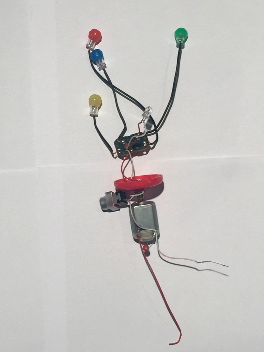
PART IDENTIFICATION : Throughout the teardown, I thought about reusing some of these fascinating parts in a future Arduino project, like the LED board. In order to understand how to use it, I search ElectronicProducts.com and discovered how every part is specifically called out including the material, manufacturing process and physicality. The wire harness, mounting bracket, connector, and the black foam rubber pad (die cut w/PSA) are all specified. Below is how just the PCB assembly was called out;

  • Location- LED PCB Assembly
  • Function- Mechanical / Electo mechanical
  • Component Family – Electro mechanical
  • Component Type – PCB
  • Quantity – 1
  • Manufacturer – OKI
  • Part Number – NA
  • Component Description- 2 Layer – FR4
  • Markings- 0507, 01-01003029-00, HH. LED BOARD, CK66 94V-0
  • Form- NA
  • IO / Pin Count- NA
  • IO Pitch- NA
  • Diameter (mm)- 10.45
  • Length (mm)- 8.70
  • Height (mm)- 0.50
  • Data Sheet Links- Visit URL

LED board.jpg

SUMMARY : similar to reverse engineering by way of a 3-dimensional schematic, this was an exciting and fascinating activity. I realized that heat must be a major factor in the considerations of designing a compact and powerful computer evident by the insulators, sinks and the distribution and air circulation. There were far more mechanical systems than expected in a digital machine and if the CD drive were to disappear, it would eliminate two motors, about four assemblies composed of up to 28 parts and save on space and the use of lithium grease for lubricating the plastic gears and slides, totaling over a hundred pieces. The MacMini was made to be repaired with exception to a few blind rivets used in the hard drive’s axis and the individual components soldered to the PC boards.

The disassembled MacMini quickly laid out.

full-teardown

Further research may include;

• electromagnetic interference EMI that is created by the device / how the MacMini was designed to shield from the EMI of other components such as a wireless keyboard and monitor.

• identifying the manufacturing processes used, including assembly and disassembly.

• creating a resource, use and waste list to understand the life cycle of this product.

• part list : calling out the size, material, manufacturer and function of each part.

• composing a step-by-step guide to disassemble and reassemble this device.

Cheers !

Chris Rand


TriceraTop-Tear(s)

This simple toy is my subject to teardown. Powered by AAA batteries it involves a rotatory motion and lit LEDs when a button is pushed.

The initial unscrewing yields the inside of the toy.

img_7509

Taking out the useful part from the casing shows a button, 5 LEDs,small circuitry,a motor and connecting wires.

img_7513

Exploring each section separately, the lighting component of the toy is shown. Consisting of 5 LEDs connected in a simple circuit.The only use of the circuit board is powering the LEDs,which are soldered to the board with wires.

img_7519

The Pushbutton type switch is used to operate the toy.These switches complete the flow of electricity when they are pressed. When a pushbutton switch is in the on position, a spring inside the electrical device makes contact with wires that will allow the current to flow. Then, when the switch is pushed down again, the spring inside retracts, and this stops electrical current, deactivating the device.

img_7517

For the rotary motion, the toy uses a brushed DC motor.

img_7521

The final layout is shown as,

img_7524

The tools used in this operation are,

img_7525

UPDATE:

Part-Manufacturing Technique

Head- Making a mould and casting

Body- Making a mould and casting

LED Lights- A semiconductor wafer,multiple wafers are joined to become a semiconductor,Ultrasonic process to clean it.

Electrical components- Include highly detailed intricate processes,although very cheap to make.

The one design choice I like is the simplicity of the button placement. Very child friendly and surprisingly sturdy.