This is an old keyboard that my family has had for many years. I decided to tear is apart because I was curious what kind of technology existed inside of it. I came to find out that there actually wasn’t as much internally as I would have thought and it only required a screwdriver to disassemble.
Components
Here is the list of what I found:
Lots of screws (actually it was all screws to take it apart)
Multiple touch sensitive boards
Rubber molded buttons
Two speakers
A metal plate and plastic molded keys, as pieces of the part you play on.
And last but not least the brains of the system, which includes the YM7137-3D chip made by Jotrin.
Everything Together
Unfortunately, I couldn’t find anything about some of the board components. Maybe it’s partially because they are built by the company and the schematics are not released. All the boards said Yamaha on them.
In conclusion I think this was an exciting project. It gave a good deal of insight into what went into a small keyboard eighteen years ago. Today, I’m guessing that a bunch of these parts would probably be smaller and able to fit better into the casing. (There was some bending of parts on the motherboard to get them to fit). I look forward to trying this process again on something else in the future.
Speaker component: Plastic 4 | Structure between the speaker and the outer shell
Speaker: Includes magnet, copper wire | Produces sound
Cover for eyes
Batteries
Sensor: Copper
Chipboard: located inside the dog’s head
Chipboard for nose
Rubber cushion for nose button
Structure holding together all components in head: includes LEDs for the eyes
On/Off chipboard
The plastic shells are made by plastic injection molding. Then, all parts are assembled, wires soldered into boards and plastic parts screwed in.
III – TOOLS USED
IV – FINAL THOUGHTS
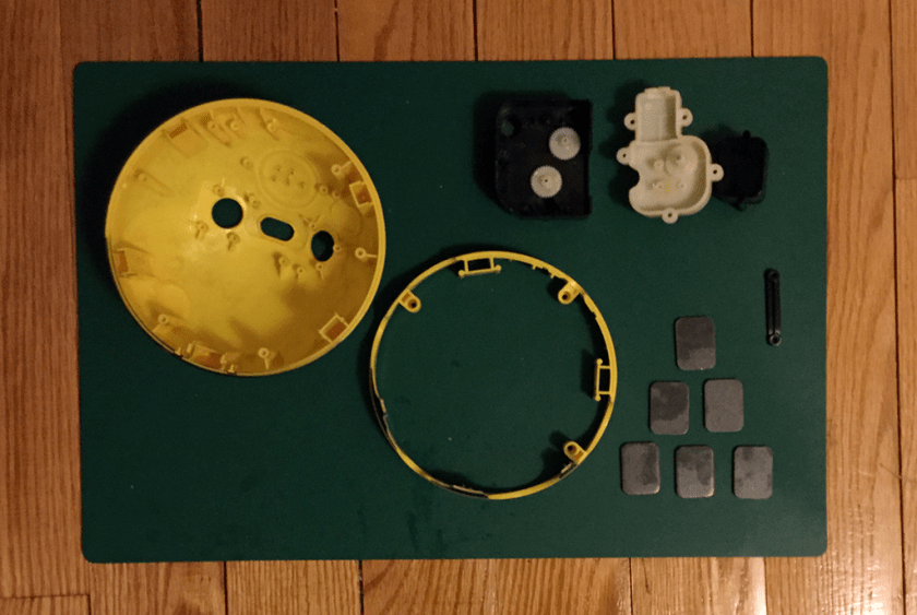
I took an interest into how the eyes of Bubblegum are designed. Instead of one piece of solid plastic shell with an iris painted on, her eyes resemble the interface of a digital clock. I thought this was rather appropriate for a battery-powered dog, as this design choice makes the dog look even more like a robot dog. One might even say that the eyes are the single visual feature that makes this toy undeniably a robot.
Another interesting feature I found was a sensor inside the head. The designer might have come up with this design based on the insight that children like to pet and stroke dogs. Putting the sensor there so every stroke or tap produces a different response was rather fitting for a toy like this.
I bought it in the E-waste Warehouse in Brooklyn. The Zapper allows players to aim at the television set display and “shoot” various objects that appear on the screen such as ducks, clay pigeons, targets, cowboys, criminals or other objectives. The Zapper is used on supported NES games, such as Duck Hunt and Wild Gunman. The Zapper could also be used on the title screens of games to move the cursor—done by pointing the device away from the screen and pulling the trigger—or starting the game (pointing at the screen and pulling the trigger).
This gun is pretty classic and stylish. When people hold it, it seems like you are holding a real gun, perhaps because of the Bob-weight. There is several components in it. The trigger structure is interesting and through the Teardown I realized this structure. And the trigger connect the sensor (kind of flip-floph) and activate the circuit board and laser light.
I chose this Walkie Talkie for kids to teardown. I did not expect the insides to be complex, although I thought the way some of the components were fixed to the walkie talkie’s main body was rough (some taped parts and cables). However this is a children’s toy and was probably design to be as affordable as possible, without putting much emphasis on the quality of materials, manufacture or function.
I used only a screwdriver to take it apart and did not need to break any parts in order to see all the components. Here are some of the parts inside the walkie talkie:
The first thing I love is the simplicity of the parts of the Guitar. The assembly of the plastic connector parts is easy and none of them have complex mechanisms. These parts are snap connectors. At times when complex systems and parts were needed in order for something to work, the designer decided to add more but still simple parts.
As the retail price for the game is low – $8.50, it seems like they chose easy assembly over minimal material.
The other thing I like are the silicon rubber conductive button pads. This is the first time I’ve seen such a thing. It’s form at different locations is what makes it fascinating! When pressing a long button – in this case – the Hero Power button, 3 button pads are used to make it work. Whereas, the tiny buttons like – the Pause button – only use 1 conductive button to complete the circuit.
I choose a funny looking kid’s toy in the shape of a bee, which turned out really interesting because it has a lot of pieces. The bee teaches kids numbers, colors, and shapes while rowling and singing.
To tear it apart I used a couple of precision screwdrivers, a multitool and a little of force because it was very well assembled. I suppose to avoid kids getting to the tiny pieces and swallowing them.
I found that many similar plastic pieces were numbered, my guess is they do that to help with the assembly process. As far as how they were manufactured most of the plastic pieces were injection molded.
The Bee has some electronics pieces which were very interesting: a motor, on and off switch, led color lights for each button and a speaker. I was able to find the data sheets, which to be honest where a little overwhelming because of all the information, but also enlighting, makes you consider how many processes and inputs one single piece goes through before it ends up in a store.
I bought this PowerBeats headphone about 2 years ago and neither the music quality nor the product quality reached my expectation (I would not recommend it) . So it stayed in my box for a long time and I decided to throw it away.
BUT before saying Goodbye, let s take a look inside!!
Two Saturdays ago, I wandered over to the Gowanus E-Waste Warehouse. It was awesome looking through their prop library of old gadgets; there were so many things in there that I wanted to take apart! Unfortunately, those items there were just for borrowing 🙁
But! I ended up picking up an N64 controller instead for this teardown project. Here, you’ll find a photo of the controller (with a few friends from Super Smash Bros. Such nostalgia, hehe). Below is a quick tutorial of the tools and steps needed to take this device apart.
My Toolkit
Prior to teardown, I gathered up a few of my tools. There are the ones that I thought I would need, though it turns out I actually only needed two of these tiny screwdrivers to take apart the controller. Pictured here are Phillips Head Screwdrivers (2), Needle Nose Pliers (1) and a Box Cutter (1).
Step 1: Take the Shell Apart
The first step here was to take the shell apart by using two different size precision screwdrivers. There were seven screws on the backside of the shell and two in the top. When the shell is taken apart, the Left/Right buttons will automatically come out.
Step 2: Remove the Joystick Portion
Once the shell is open, use a precision Phillips Head Screwdriver to remove the 3 screws from the joystick portion of the controller. I had some trouble with the bottom screw, as the head was a bit busted, so I ended up unscrewing the ones on the left and the right and pulling it off, which came apart easily.
Step 3: Detach the Circuit Board, Joystick Portion, and Buttons
Once the circuit board and joystick are removed, you’ll see various little rubber padding strips that look like legos. Remove these and you’ll have a shell with some of the button still attached. They’ll be easy to pop out one by one.
Step 4: Take Apart the Joystick
The joystick is easily the most complicated part of this controller. There are several moving pieces to it, including a spring and little wheels that enhance movement. It was surprising how many components were needed to create this joystick motion; you can see that there are 7 parts to that one capability.
Here are all the parts removed:
And another photo without parts labeled…
Timelapse Recap Video of Teardown:
**edit** Sept 27 2017 @ 9:43am
Adding in information on the technical parts inside the N64 controller – apologies for not doing it before!
Circuitboard CFS8120-200010-02 – It looks like this printed circuit board may be specific to Nintendo and this controller.
MX1720FC C9721 MD67470 – specific Nintendo chip for this controller, made in Taiwan
YG-H2 – There are several of these chips in there, one for the left button, one for the right, and one for the Z directional button on the back of the controller. I couldn’t find too much information on them, but I am guessing they are for directional changes on the controller.
CFP8109-110010-01 – I unfortunately couldn’t find any information on this specific chip through several Google searches, but judging from its attachment location to the circuitboard, I think it may have had to do something with the joystick movement.