Light Up “Superhero” Yoga Mat

medemonstrating

Before I set out to make my yoga superhero mat, I did some research and found a burgeoning yogi/superhero movement. Check it out here! There’s a pose in yoga called “Superman” and yoga helps people find their superhero within.

yogamatinprogress

So first I had to write some code to make a yoga mat with velostat sensors that lights up. I took inspiration from these Firewalker LED sneakers and then made some adjustments so that the different pins corresponded to different velostat pads. You can see the prototype here.
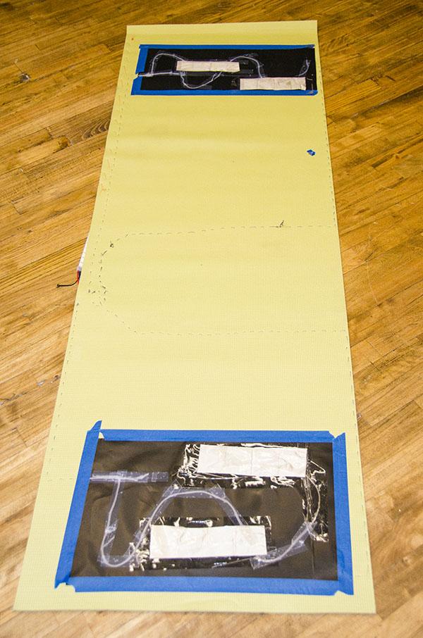
Next, I started to build the mat. I soldered the LED strip on the flora board and used conductive thread to sew from the sensors to the flora board. The code I wrote is for three sensors, but I used two so that things wouldn’t get too messy.

I used conductive thread so that the mat could still easily be rolled up and transported.
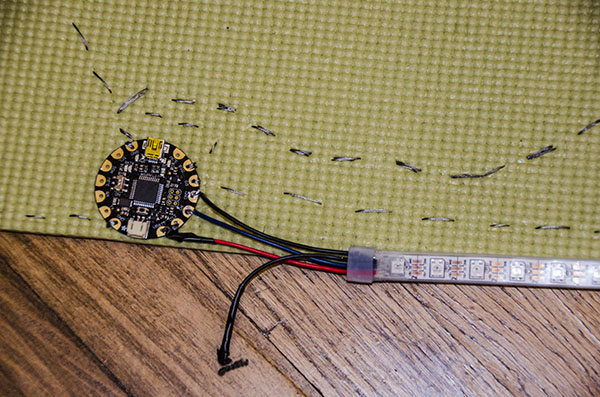
closeup

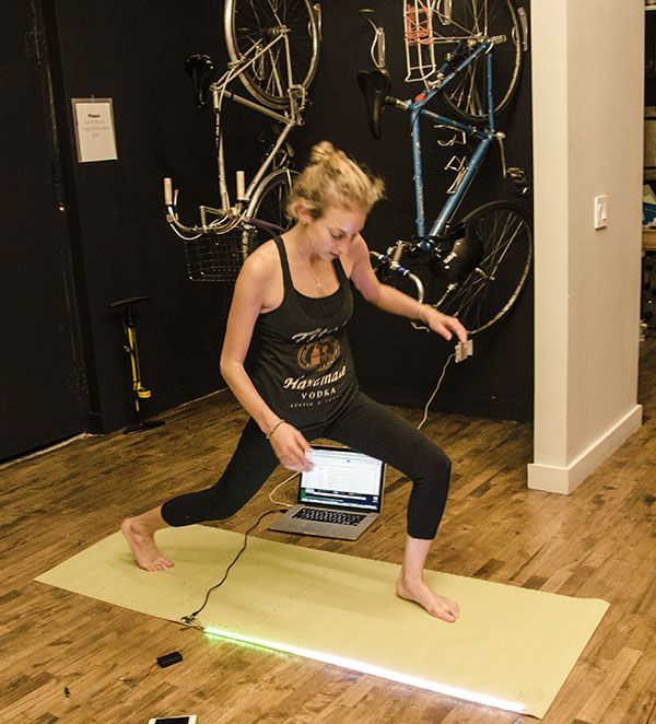
Now when I do yoga, the mat changes colors when I move around. I could see that this would make yoga more fun for kids and might propose the idea to Headstand. I also think that this would make for a rad yoga dance party! MC Yogi would LOVE it.

Screen Shot 2013-10-07 at 9.37.33 PM

Check out the code and make your own light up superhero yoga mat!

#include <Adafruit_NeoPixel.h>

const int analogInPin = A9; // Analog input pin that the potentiometer is attached to
Adafruit_NeoPixel strip = Adafruit_NeoPixel(60, 6, NEO_GRB + NEO_KHZ800);
int sensorValueR = 0; // value read from the pot

int sensorValueG = 0; // value read from the pot
int sensorValueB = 0; // value read from the pot

const int ledPin = 7;
void setup() {
Serial.begin(9600);
pinMode(9, INPUT);
digitalWrite(9, HIGH);
pinMode(12, INPUT);
digitalWrite(12, HIGH);
pinMode(10, INPUT);
digitalWrite(10, HIGH);
strip.begin();
strip.show();

}

void loop() {
sensorValueR = analogRead(analogInPin);
Serial.print(“sensorR = “);
Serial.print(sensorValueR);
sensorValueG = analogRead(11);
Serial.print(“sensorG = “);
Serial.print(sensorValueG);
sensorValueB = analogRead(10);
Serial.print(“sensorB = “);
Serial.println(sensorValueB);

int r=0, g=0, b=0;
if (sensorValueR > 55) {
r=20;
}

if (sensorValueG > 352){
g=20;
}
if (sensorValueB > 65) {
b=20;
}

colorWipe(strip.Color(r, g, b), 25);

}

void colorWipe(uint32_t c, uint8_t wait) {
for(uint16_t i=0; i<strip.numPixels(); i++) {
strip.setPixelColor(i, c);
strip.show();
//delay(wait);
}
}

Flash Fire Night Light

Hi! This my final project!

The materials I used are as follows:

1.Arduino UNO board

2.color strip

3. wool felt fabric

4.9V battery

At first, when I put the pixel light strip to computer, I find that my whole light strip just

lights six lights which make me crazy. And my computer often pop-ups the warning:

Image

Finally, Becky and Tak help me to solve that problem, the reason why there is only six lights light is that the 60 pixels at full brightness draws a lot if power, and Tak helps me to change Arduino UNO board from the flora board.

As my conception, I need to use the match to ignite the fire. However, I realized that the motion sensor need to move like change the X/Y/Z axis constantly. But my fire can`t move! After that, I figure out  to use the resistant to turn on the fire. I make a code which I just touch sightly to the resistant, and than the fire can be ignited!

QQ截图20131008003117

IMG_0776 IMG_0780 IMG_0783

Image

ImageImage

Image

I use the embroidery machine to make a fire logo on the surface of my matchbox.

This is the code:

#include <Adafruit_NeoPixel.h>

#define PIN 6

// Parameter 1 = number of pixels in strip
// Parameter 2 = pin number (most are valid)
// Parameter 3 = pixel type flags, add together as needed:
// NEO_KHZ800 800 KHz bitstream (most NeoPixel products w/WS2812 LEDs)
// NEO_KHZ400 400 KHz (classic ‘v1’ (not v2) FLORA pixels, WS2811 drivers)
// NEO_GRB Pixels are wired for GRB bitstream (most NeoPixel products)
// NEO_RGB Pixels are wired for RGB bitstream (v1 FLORA pixels, not v2)
Adafruit_NeoPixel strip = Adafruit_NeoPixel(60, PIN, NEO_GRB + NEO_KHZ800);

void setup() {
strip.begin();
strip.show(); // Initialize all pixels to ‘off’
}

void loop() {
int n=analogRead(A0); //读取模拟口数据
if(n>0) //如果人体触摸了N就不为零,触发
{
for(int a=0;a<50;a++) //循环50次,200毫秒X50次=10秒 亮灭亮灭持续10秒效果
{
colorWipe(strip.Color(255, 0, 0), 0); // Red 亮
delay(100);//延迟100毫秒
colorWipe(strip.Color(0, 0, 0), 0); // noLight 灭
delay(100);//延迟100毫秒
}
}
colorWipe(strip.Color(0, 0, 0), 0); // noLight
}

// Fill the dots one after the other with a color
void colorWipe(uint32_t c, uint8_t wait) {
for(uint16_t i=0; i<strip.numPixels(); i++) {
strip.setPixelColor(i, c);
strip.show();
delay(wait);
}
}

void rainbow(uint8_t wait) {
uint16_t i, j;

for(j=0; j<256; j++) {
for(i=0; i<strip.numPixels(); i++) {
strip.setPixelColor(i, Wheel((i+j) & 255));
}
strip.show();
delay(wait);
}
}

// Slightly different, this makes the rainbow equally distributed throughout
void rainbowCycle(uint8_t wait) {
uint16_t i, j;

for(j=0; j<256*5; j++) { // 5 cycles of all colors on wheel
for(i=0; i< strip.numPixels(); i++) {
strip.setPixelColor(i, Wheel(((i * 256 / strip.numPixels()) + j) & 255));
}
strip.show();
delay(wait);
}
}

// Input a value 0 to 255 to get a color value.
// The colours are a transition r – g – b – back to r.
uint32_t Wheel(byte WheelPos) {
//if(WheelPos < 85) {
return strip.Color(WheelPos * 3, 255 – WheelPos * 3, 0);
//} else if(WheelPos < 170) {
// WheelPos -= 85;
// return strip.Color(255 – WheelPos * 3, 0, WheelPos * 3);
//} else {
// WheelPos -= 170;
// return strip.Color(0, WheelPos * 3, 255 – WheelPos * 3);
// }
}

Please enjoy the amazing video!!!

http://www.youtube.com/watch?v=IPZyzRi0vVY&list=HL1381207377

Illuminadrum

DSC_0626

Drum

Sourced a drum after 4 hours of roaming Manhattan. This one was loud, meant to be played kids, was open from the bottom to give me space to fit electronics.

Started out playing with different codes http://www.arduino.cc/en/Tutorial/Knock after making a temporary circuit on Arduino Uno. It was fun to play with the piezo sensor. I wanted to ambitiously change the brightness with the impact on the sensor. I was almost there but the light wouldn’t go out in static position. Learnt about Mapping, countdown etc in coding.

Untitled-1

DSC_0630 (2)

DSC_0634

Soldered the LEDs in a parallel circuit

Finally used a Digital interaction instead of Analog one. Code:
// these constants won’t change:
const int ledPin = 11; // led connected to digital pin 13
const int knockSensor = A0; // the piezo is connected to analog pin 0
const int threshold = 1; // threshold value to decide when the detected sound is a knock or not
// these variables will change:
int sensorReading = 0; // variable to store the value read from the sensor pin
int ledState = 0; // variable used to store the last LED status, to toggle the light
int mapFade= 0;
int brightnessLED = 0;
int countDown = 0;
int fadeDown = 0;

void setup() {
pinMode(ledPin, OUTPUT); // declare the ledPin as as OUTPUT
Serial.begin(9600); // use the serial port
}

void loop() {
// read the sensor and store it in the variable sensorReading:
sensorReading = digitalRead(knockSensor);
// if the sensor reading is greater than the threshold:
if (sensorReading >= threshold) {

// send the string “Knock!” back to the computer, followed by newline
int cSensorReading = constrain(sensorReading, 0, 50);
mapFade = map(cSensorReading, 0, 50, 0, 255);
brightnessLED = brightnessLED + mapFade;

digitalWrite(ledPin, HIGH);

Serial.print(“knock!”);
Serial.println(sensorReading);
Serial.print(“constrain”);
Serial.println(constrain(sensorReading, 0, 10));

} else{digitalWrite(ledPin, LOW);}
delay(10); // delay to avoid overloading the serial port buffer
}

DSC_0010

Ad_blue man group

SEE THE VIDEO 🙂

http://www.youtube.com/watch?v=PQ_t-vmfd3I&feature=youtu.be

Thank you

Turn on: Plushie “Big Head” project

My interest for this project began with exploring how touch can bring so many emotions and physical reactions. I see my Plushie in a child abuse center, were this might be a prop to mediate a conversation about abuse. I also see this plushie as a prop for sex education and seeing how touch can cause arousal in the sex organs, which can include the brain. This plushie is activated by pressing on the right hand, which activates a LED light near its “private parts”. Ideally I would like to place LED lights in its head, and/or heart that would light up when you hold its hand. Another idea was to have it activate it’s heart, when you kissed it.

I began with a reference plushie that I have been working for some years.

CIMG4714

I continued with the firewalker code and with the help of my colleague Jung I was able to get this code to work. After I tested the prototype circuit, I was ready to make my plushie. The plushie is made out of Green and blue knit, Flora board, Velostat, LED, and wire.

DSC_0604 DSC_0606 DSC_0687 DSC_0688 DSC_0692 DSC_0696 DSC_0697 DSC_0707

After several attempts, I was unable to get the plushie to work with the battery pack. The only way it would stay on and activate the LED would be if I had it plugged into my computer. I decided to continue the plushie and tested on a male and a female volunteer.

DSC_0708 DSC_0715DSC_0714DSC_0716 DSC_0718

In these two cases I had the volunteers touched the plushie on its right hand, in order to activate the LED.

I had different responses, the most interesting coming from the female which asked “why it light up there?” Her expression was of distaste or hesitance, however she was a great volunteer and continued with the process.

What I learned is that touch and how it’s given is very significant in generating emotions. The location of the light was deliberate but I did not expect the various reactions to its placement. They ranged from humor to discuss of the location of the light. I also learned that placement of the “squeeze” is very important, and that my placement of it didn’t correlate my message.

I would like to experiment with different locations of the LED and there intensity. I would also like to place the activation point in different locations and see how individuals reacted.

TSHIRT + NIGHTLIGHT

TSHIRT + NIGHTLIGHT, I began to think about what the ideal lighting element would be for a constant, all-night glow—something a person could sleep to. I looked to traditional table lighting for inspiration, a recognizable silhouette. Intersecting acrylic and hand-sewn materials resulted in a unique take on traditional night-lighting.

materials: cloth from two t-shirts, six flora pixels, flora board, battery pack and acrylic plastic

processes: sewing, soldering, coding, and lasercutting

Image

Image

Image

Soldered 6 flora pixels together for coding.

Image

Image

The original shirt was too dark to allow the LEDs to shine through, chose white.

Image

Lamp in action. The flora pixels (6) are located in the white shade while the battery runs from the brown base to the flora board.

Image

Image

The battery pack is sewn into the base, I extended the original battery wire so that it would reach the lamp shade.

Image

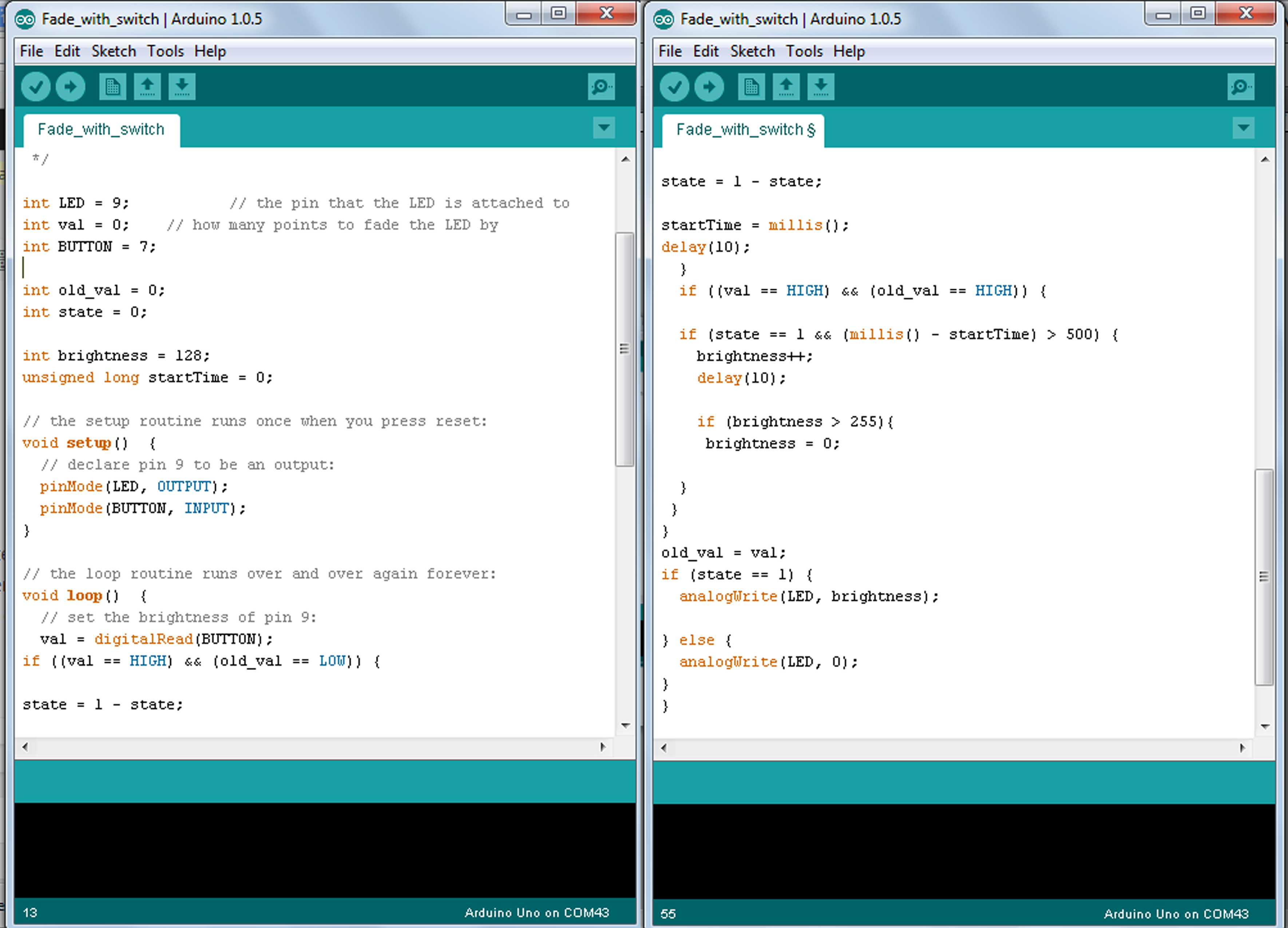
Led FADE

Fading the Led —-

Fading the Led with a switch —–

code

Then I was playing with a infra-red proximity sensor. I wanted to change light color according to proximity, but that didnt happen. I did however learn how to read the readings on the serial monitor, which shows that it is working and reads different numbers and different proximity to the sensor.

Automatic Wallet

Wallets were once considered containers for paper currency. That has since changed, today what you carry is not as important as how much information it retains. Introducing the Automatic Wallet…

ID ScanID Scan_back

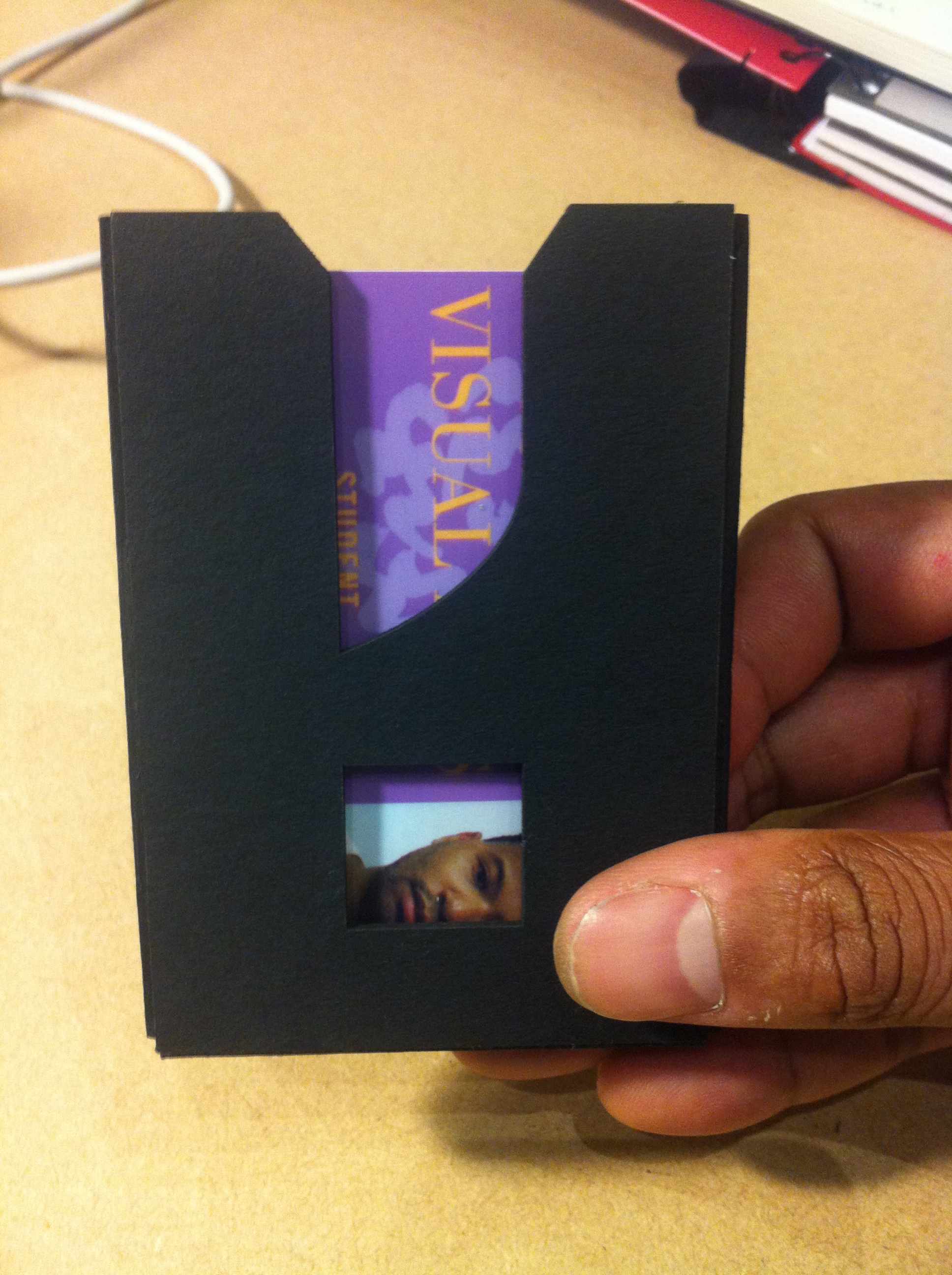
A wallet that automatically scans business cards and receipts, reducing pocket clutter.

 The Process

Mind Mapping_sketching Sketching

I began by looking up the definition of what “wallet” means, then I did a mind map of how that definition has evolved over time.

Painpoints

image

Next I asked my fellow classmates to share some painpoints about their wallets. What I found out is that men and women have very different needs.  But the common attribute is that both groups want to reduce clutter.

My hypothesis: Wallets are filled with junk. People want to digitalize things like receipts and business cards quickly so they can access them later.

Solution

image

My concept is based on the small card reading technology of Square and a small ID holder wallet. I’ve decided to create a men’s wallet that can scan business cards and receipts so that information can be accessed later. I sketched a couple of ideas and looked for some inspiration online. My final design incorporates an LCD screen that displays credit card balances and newly inputted contact details. The information can then be portered to a person’s email or phone contact list.

Prototype

image

I started out by making a cardboard version by hand. The results were effective but a bit crude.  The edges frayed and the integrity of the fold was compromised because of the scoring.

image

To refine the design I used a laser cutter. I created an illustrator file that contained the blueprints and then printed out the design several times, exploring different cardboard materials and thicknesses. Then I used glue to put the components together.

Next Steps

I’d like to insert a real LCD screen and Square card reader into a wallet. I’d also like to bind the prototype with leather to make the material more durable. I found several leather shops in the garment district that have thickness that will house a small LCD screen.

/George

Cardboard Party Favor

I call these cardboard party favors “PLATS”. They provide a platform for fun, memory, and connection. After researching party favors, I focused on the question “Why do we give party favors?”

Here is my process:

I began with exploring  food experiences that could fit the multiple contexts that party favor are used in. What I found interesting was the act of sharing, and connection in the situations among the participants. I feel that we can take away more from the experience than a simple party favor. I sought to explore the connections between the quest, and host that could activate the space shared.

“PLATS” are easy to make. All you need is cardboard and some colorful string. You can work with different shapes to change it up. You can make as many to include all your party or select groups. A easy fun way to create an experience that they can take away and share.

.DSC_0011DSC_0016DSC_0018DSC_0026DSC_0041DSC_0058DSC_0082DSC_0128DSC_0139 DSC_0123DSC_0126DSC_0124DSC_0142

Tin Can/Lamp Steve H.

TinCanMovieRevised             IMG_0763

Concept:  A Tin Can Lamp embodying three primary functions of “lamp-dom”, Light, Heat, and Illumination.  The light is an obvious by-product of the electrical excitation of the bulb filament.  Heat is a less recognized output of this process and indicative of the energy waste inherent in incandescent light bulbs (soon to be outlawed for this very reason).  This wasted energy typically evaporates unnoticed however the design of this lamp captures the energy as movement, the rising heat providing motive force via the fins cut into the top of the inner can.  This rotational movement in turn facilitates the third elemental function of Illumination via the message “Free Your Mind” animated through letters cut into the inner can and which are read through slots cut into the wall of the outer can.  The principal is borrowed from the Zoetrope, an early mechanical animation device that takes advantage of human persistence of vision to create the illusion of motion from a sequence of still images, and which was the precursor to the modern film projector.  By incorporating the Zoetrope I pay homage in two ways to my filmmaking career by referencing the film projection apparatus as well as my first film internship at Francis Ford Coppola’s Zoetrope Studios in San Francisco.  As the first project created in pursuit of my MFA in Product Design which paves the way to a new future the piece symbolically extinguishes the lights on my former career in film as the message implores me to seek new challenges.

Structure:  The lamp includes a large tomato can acquired from the 7th Avenue pizza deli, a smaller tin which contained butter cookies, a scrap wood base, a porcelain flush mount bulb socket salvaged from the ceiling of my garbage alcove at home, a repurposed two prong lamp cord, plug, bulb, and a harp from a box of miscellaneous lamp parts that my wife keeps in the basement.  All parts are salvaged and repurposed to remain structurally and ethically consistent with the inherently recycled nature of the assigned “tin can” material.

IMG_0756

Research:  An internet search of Tin Can Lamp yields hundreds of examples, many of them beautiful, ornate, and highly functional.  Given the ubiquity of these artifacts I sought rather than to add my own ornamental and/or functional element to the oeuvre, to focus on essence and meaning as the primary function of my design.  I researched the manufacture of tin cans, their history, and discussed the essence of lighting and lamps with several classmates.  Professor Andrew Schloss who happened upon our conversation about lamps revealed that he had spent many years designing lighting for Artemide and lamented the fact that they so often neglected the light in favor of the form of the thing (the lamp) itself.  As he lost himself in this lament and excitedly discussed the nature of lighting he blurted out “lighting is 3D plus magic”.  I really liked this idea and in thinking of “magical” applications of light I remembered the Zoetrope and the magical way it used light to reproduce reality in an entirely new manner and that this led eventually cinema.

Prototyping:  Initially I intended to create a single can system that rotated and projected a message on the surrounding walls.  I created a cardboard model with 1/4” thick lettering and discovered that the projected shadows were illegible at any distance.  A second model with very thin lettering cutouts provided a focused projection but only if the lettering was placed about 20 to 30 inches from the light source.  This would only be possible if I constructed a large ring out of several flattened cans so I rejected this method and turned my attention towards a direct view of the message rather than a projected view.

IMG_0759 IMG_0749 IMG_0752 IMG_0746

I reversed my original model (the projection required the letters to be backwards in order to appear correctly on the wall) and I built a larger outer “can” from paper that had slits through which to view the lettering one at a time as the inner tin rotated.

I cut several fins into the plastic lid from a coffee can to test the rotational force of the rising heat.  I filed the screw on the top of the harp to a sharp point upon which to balance the lid and the reduced contact area also greatly reduced the friction.

IMG_0753

The plastic finned lid didn’t rotate however and I felt this was because the cardboard and tape model was too imbalanced and imprecise.  I had to move on to a metal version in order to truly test the phenomenon.  The 10oz coffee can standard proved to be too small to fit over the hips of the harp so I had to find another tin that was one size larger in diameter.  I procured a cookie tin that had the disadvantage of being very short and therefore much less vertically stable than the coffee can was during my preliminary balance testing, but I decided to move ahead as it otherwise fit the model.  I tried to carve the letters out with an auger bit and the flexi shaft.  It was really unwieldy trying to cut and in fact I blew a big hole into the side of the tin so I opted for the drill through pinhole method of lettering that you see in the final prototype.

IMG_0760

The fins were cut using a jewelers saw (thanks to Heath for coaching me with this and for sacrificing several of his sawblades to towards my education!) and I also used the saw to cut the slot in the side of the outer can.  After a bit of sizing and drilling into the base the assembly was put together.

IMG_0777

Unfortunately the heat from the 100 watt lightbulb didn’t create emough motive force to make the tin rotate (although it is enough to quickly heat the tins so as to cause pain if you touch them).  I attribute the lack of rotation to a combination of excessive weight and a lack of balance which creates an “uphill” push for one section of the rotation and am convinced that a balanced model with a deeper can will rotate from the rising heat (while creating even more scalding hot tin).  This prototype offered enough manual functionality to test the rotational revelation of the message and to photograph the above GIF simulation of the system’s functionality.  As you can see the message is sequentially revealed but two significant design flaws also became evident.  I need to cut the top fins in the opposite orientation as the heat risen motion as is will reveal the letters backwards.  The other is that this structure, while it provides the desired illumination and it is revealed sequentially through the slot in the side, it inadvertantly subverts the use of persistence of vision in favor of a mechanically revealed sequence of letters.  Not so magic after all.