Guitar Hero Controller Teardown

The Guitar Hero Wireless controller for the Xbox.

1.png

Taking apart a Guitar Hero controller starts with the removal of the neck via a release latch on the back. (#2)

2.png

Leaving two separate pieces. The Neck and the Body (#3)

3.png


THE NECK

The neck opens up via 11 Torx screws on the back of the piece and easily separates to reveal the components inside. (#4)

4.png

The electronic components and connector are then easily lifted out of the housing (#5+6) and contain circuit boards for the fret buttons, the fret slide, and the neck connector.  More on these specific components later.

5b.png

6.png


THE BODY

7.png


Access to the Body’s components necessitated prying up the printed fretboard panel (#8) to reveal the front of the injection molded piece. 16 Torx screws were removed (#9) to open the case and gain access to in innards (#10)

8.png

9.png

10.png


The interior electronics in the body consist of 7 separate circuit boards as well as the whammy bar components and a battery box. (#11)

11.png


ELECTRIC COMPONENTS

Nearly all of the electronic components inside the guitar hero are small simple circuit boards that are connected via ribbon cables. Each board is focused on a specific task and method of interaction.

Starting from the top of the neck, the first board is the Fret Button Board (#12). It is a simple circuit closing board where the backs of the fret buttons touch down on the board to close a circuit.

12.png


The next board down the neck is the Fret Slider. (#13) and contains the not only the touch pad element but an IC chip as well (#14).

13.png

14.png


The Neck and body connect with two boards, one on the Neck (#15) and one in the Body (#16). The physical connection is done with a roughly USB sized plug (#17+18)

15.png

16.png

17.png

18.png


The Strumming Plate (#19+20) is next traveling down the guitar and is comprised of a circuit board containing just two spring loaded buttons which are pressed with strumming up or down on the guitars interface (#21+22).

19.png

20.png

21.png

22.png


The Start/Select controller, much like the Fret Buttons is an assembly of a circuit boar and contact buttons (#23+24)

23.png

24.png


A direct connection with the XBox is facilitated by the Controller Connector (#25+26+27)

25.png

26.png

27.png


A button to activate the wireless connection and an expansion port are contained on the Power Switch board (#28+29+30) The expansion port uses the R45 connector – similar to a standard telephone terminator.

28.png

29.png30.png


The Whammy Bar mechanism is a dual-direction spring-loaded assembly that drives a potentiometer (#31+32+33)

31.png32.png33.png


The D-Pad controller, much like the fret buttons, is another simple circuit board (#34+35) with contact points which has a silicone contact pad and the physical d-pad interface laid on top of it (#36+37).

34.png

35.png

36.png

37.png


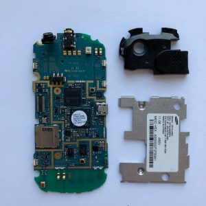
The Main Board contains the meat of the processing components (#38+39) and is the hub connecting all of the other boards within the entire controller (#40+41).

38.png

39.png

40.png

41.png


The Majority of the Integrated Circuits on this board appear to be microsoft / xbox custom chips (#42+43+44) but also includes a 7318 KRAAC (#45)

42.png

43.png

44.png

45.png

Thank You.

Gameboy Teardown

I teared down a Gameboy I used before. It have hundreds of games inside and several buttons to control it. It can connect with TV to play games on the TV.

Here are the photos of this Gameboy.

IMG_77741

IMG_7782

Disassembly process

Step 1. I used the screwdriver to unscrew the screws on all sides that holds the back of Gameboy. And it showed circuit board inside.

IMG_7797

Step 2. Then I used the screwdriver again to unscrew the screw which in the middle of circuit board for fixation.

Also there are four plastic stick to support the circuit board.

IMG_7803

Step 3. After that, Gently open the circuit board. Inside the Gameboy is look like this:

IMG_7808

Step 4. I took all the parts out around the button.

There is a layer of rubber gasket under the buttons which connect it to the circuitboard.

IMG_7819

Then all the parts Disassembled.

IMG_7832副本


The material and manufacturing techniques/equipment of the parts

Front Panel: ABS Plastic, Injection moulded;

Back Panel: ABS Plastic, Injection moulded;

Battery Panel: ABS Plastic, Injection moulded;

Circuit Board: glass-fiber reinforced and copper foil;

6 Buttons: ABS Plastic, Injection moulded;

Rubber gasket: Conductive rubber.


Tools Used

Screw drivers, Knife.


My findings

The first thing that I interested in is the rubber gasket. When I took out of circuit board, I was so curious about the part of button, because under the button there is a layer of rubber gasket. I haven’t seen this before and it felt differently when I first touch it. And after some research about it, I came to know how the button works.

Another thing is about the sound speak. There is a volume controller we can choose the suitable volume for ourselves, and the volume controller and speaker are separated to two parts. Even though I have broken it up, I just don’t know how it works so I am quite curious about it.IMG_7830

Robo Battle Dragon Teardown

DSC00139

DSC00226

Overview

This is a teardown of the Sharper Image Electronic Action Robo Battle Dragon. It drew my eye because it’s super rad but also has a nice cute factor. I also thought that it had much more cool features like sounds and the ability to battle other robots, but the only electronic things it does is walk and have a red light on its chest. Other than that it has a spring loaded mouth to hold things, segmented tail that swings while it walks and a head that turns slightly from side to side

DSC00141

Step 1

Make sure our small friend is turned off. Remove screw then, battery cover and batteries from underside.

Step 2

Remove two screws from cover on bottom of head, that will allow the jaw and spring to come off as well as the top of the head to pop off. Two screws on the underside of the top piece hold on the piece with the rubber teeth.

Step 3

Find the two white plugs on the side and pop them out. Remove these two screws and pop the white cover off over the wings.  You can also yank the arms out with a little bit of effort.

Step 4

Remove the three screws from the tail.  This should allow the tip and smallest segment to come out.

Step 5

Pop the plug out on the side of the tail and remove that screw. Then remove any other screws from the side of the body.  This will allow the other sections of the tail to come out.  It will also release the neck portion and allow the body to split in half.

DSC00178.JPG

Step 6

Notice in the center of the body where the leg is mounted.  It has a boss that fits to the side of the motor.  The motor provides a spinning motion to both legs and creates the walking action. We can remove the one screw within the boss and the leg will come out. Removing the rest of the screws on the leg allows it to split apart.

DSC00181

Motor GIF

Step 7

Remove the two screws at the base of the fin.  Grab a pair of pliers and the pin that is part of the walking mechanism will come out easily.

Step 8

Pull the electronic assembly out, we’ll analyze this later.  This side of the body will come apart the same as the other.  Note the two extra longer pins that hold the motor in place and be sure to pull those out too.

Step 9

Examine the electronic assembly.  This is where the grand disappointment is—no sound chips, no speakers, no sensors to allow it to actually fight other robots, just two AAAs, an LED wired in parallel with a motor, and a slide switch to control on/off.

DSC00215

Conclusion

I had high hopes for the Robo Battle Dragon, but it turned out to be much simpler than I thought. but two things I found interesting were:

  1. The tail.  The method they used to segment the tail was pretty cool.  I’ve never seen injection molded pieces used with a pin like that before to create a series of hinges.
  2. The white side panels.  These were fairly cleverly constructed to hide a majority of the screw holes on the body.  I was surprised that the two plugs covering the screws were only held in via a pressure fit and no adhesive was used.  It’s interesting that they also used a series of clips along where the spine would be.

DSC00220

kSafe Lid Tear Down

For this assignment, I took apart the kSafe Time Lock Safe lid. The product is a plastic container with a lid that the user can set a timer with a large round dial button that activate a locking mechanism. I was curious to explore how the electronic and mechanical systems in this lid worked together to create this lock system. The shell of the lid is made of a hard red plastic with a top and bottom main piece pressed together securely, making the initial deconstruction rather difficult. I had to use a chisel and hammer to pry the two outer pieces of the lid open.

Process Shot 1

Here is a timelapse of how I disassembled the object after hammer the outer skeleton apart in the woodshop:

Object Parts:

MakingStudio_Assignment1_AerialShot

  1. Bottom cover where mechanical gears are placed
  2. Top cover with dial button and digital screen frame
  3. Pieces of the slide-out lock mechanism
  4. AA batteries and battery cover
  5. Dial button
  6. Wheeltrain gear parts with large wheel and smaller wheel containing mechanical motor parts
  7. Digital screen and plastic cover that secured screen to control board.
  8. Control board with M430F412-REV microchip. Connected to touch sensor for button dial.

IMG_7510

Process Shot 2Process Shot 3

Interesting Finds:

  1. I was surprised at how simple the electronic and mechanical setup of this object is, but it made it easier for me to track how the locking mechanism takes place and how all the components work together.
  2. I am interested in learning more about the touch sensor that activates the locking mechanism. It’s also connection to the digital output of the screen as the timer is set through turning the dial.

Cordless Phone Tear Down

I would like to present the tear-down of a Panasonic digital cordless phone with a base unit and handset

The initial breakdown only required popping off the handset battery cover (a) and using a Philips screwdriver to take out screws from the back covers

The front and back covers of both devices required just a flathead screwdriver to separate.
5
Initial view of the internals

Starting with the base unit, I first detached the motherboard using wire cutters, although one could use a desoldering wire as well.
6.jpg

The motherboard:

7
Front
8
Back

9Directly below the motherboard was a button board that contains button contacts over which the button pads sit.  I removed the screws to free the button board and charging dock.
10

14There are three additional parts that were initially attached to the motherboard:

  1. RJ11 Phone socket
  2. DC Power Jack
  3. Speaker

Next up, the handset!

15

I used wire cutters to free the motherboard from the back speaker, which was held down by a plastic part that twists off.

I then removed the screws attaching the motherboard to the front cover and took the battery contacts and charging contacts off.

Here are some of the parts I identified right away:

  1. Motherboard
  2. Button pad
  3. Battery contacts
  4. Charging contacts
  5. YD2052-72 Loudspeaker

20

From the front of the motherboard:

  1. Speaker
  2. Monochrome LCD Display Module
  3. Electret Microphone

21

Some additional parts from the base unit:

  1. Top cover
  2. Back cover
  3. Charging port
  4. Button pad frame
  5. Button pad
  6. Button pad
  7. “Play” Button pad

My Findings

In the process of completing this tear-down, I noted that the handset back speaker and base unit speakers were attached using a plastic piece that twists off easily.  I am interested in learning why these particular components were not secured using screws as the other parts were.  I also found it rather difficult to identify the smaller components on the circuit part without a deeper understanding of electronics, so I’m eager to gain the knowledge to improve on this later on.

Headphone Teardown

I got a broken fancy Beats headphone from a friend, which is cool, cause I always wanted to see what it’s like inside a headphone. And Beats by Dr.dre has always been a super popular brand, it’s more of a fashion accessory than an entertainment device to me.

Step 1. Open the shell

-Take out the rubber pad

-Take out the leather cover

I enjoyed playing with the joint part, the machined aluminum

does a great job of connecting the speaker with the headband.

Step 2. Remove the screws

Left- They glued it after it has been screwed, so it took me a lot of effort to unscrew the metal part.

Right- the speaker part has been tightly glued, it can’t be taken out.


Step 3. Tear down the rest part using hand

Interesting findings

  1. I like the way the inner plastic piece made, it holds all the cables in place steadily.
  2. Surprisingly, instead of using tenon, they glued almost every part of the components. I was expected that there will be a lot of clever processing method.Overall, even though there were some differences from my expectation, I still learned a lot about how does a headphone works.

iHome Teardown

For this tear down project I found an old iHome iPL8 Charging Stereo FM Clock Radio with Lightning Dock.


Features include:

  • USB Port
  • AUX line
  • Alarm “Wake/Sleep” function with iPhone/iPod music or FM radio
  • iPhone charging doc
  • Digital time display
  • Speakers (Reason8 Speaker Chambers)
  • Materials
    • Plastic Injection mold
    • Matte Metallic Mesh
    • Foot pads
    • Screws

Part 1

I approached the iHome from the underside, removing the Lithium Watch battery first and proceeding with the 4 visible and accessible screws. After those were removed I discovered there where two more screws hidden beneath the foot pads. Removing those allowed me to open the case.


Part 2

From there I encountered a layering of circuit boards and electronic components; separated by injection mold casings or foam padding.  All of these were well-organized and neatly packed into the case. Each part was easily broken down with a tiny Phillips head screw driver.


IMG_9920
All interior components

Part 3

At this phase you can clearly begin to see the different parts of the iHome (i.e. Digital clock, speakers, iPhone port) and how they connect to the main circuit board so I started breaking them down one by one.

Speakers:


  • Materials:
    • Speakers – SRS TrueBass expanded bass circuitry. sealed speaker, magnetic and glued shut. ( YDF4304-A122M1-131)
    • Rubber
    • Injection mold plastic
    • Wiring
    • Foam
    • Screws

iPhone Port:

IMG_9933

  • Materials
    • Injection Mold Plastic
    • Circuit board
    • Screws
    • Springs
    • iPod jack

Digital Clock Display Components:

IMG_9939
Clock/Music control Board
IMG_9940
Digital Clock Display components
IMG_9941
Digital Clock Screen Display components
  • Materials:
    • Printed circuit board RoHS, including solder-stop and marking print.

    • Flexible Flat Cable Tape

    • Clear Plastic Screen
    • Textured Plastic plate with silver foil taping, sandwiched in paper.
    • Tinted Glass plate with injection mold plastic casing and framing
    • Circuit Display board.

The main circuit board with microchips:

img_9942.jpg

IMG_9946
All Parts

Materials in total:

  • Injection Mold Plastic
  • Electric wiring/cables
  • Lithium Battery
  • Circuit Boards (with soldering)
  • Flexible Flat Cable tape
  • Speakers – YDF4304-A122M1-131 (magnets?)
  • Foam
  • Glue
  • Screws

Tools Used to Teardown:

  • Tiny Phillips Screw
  • Pliers
  • Wire cutters

Parts/Chip info:

  • STA369BWS – From STMicroelectronics – Audio Amplifiers /Audio Subsystems.

  • AP918 – Flash Micro controller with LCD drive for USD audio application.

  • SS32 – S310 Schottky Rectifier – electrical resistance

One Design element I think it interesting is the speaker design. As a consumer who doesn’t understand really much about how speakers or electronics are made, the exterior design of the speaker mesh gives me the feeling that there is this giant, “surround sound” speaker affect inside my iHome. In reality there is just a L and a R speaker. It’s a bit of smoke and mirrors but I think it’s a good visual trick.

A second design element I think works really well is that the iPhone jack is set into “pins” so that the device can rock front and back when it’s connected to its port. I think this is a fairly simple thing to add into a design but it smart because probably means the components aren’t snapping or breaking when the device is put on or taken of.

Thanks I hope you enjoyed my teardown!

Stephanie

Samsung Intensity II Teardown

Project 1 Knolling_back_labelled

Project 1 Knolling_front labelled.jpg

Components:

  • A. Back casing with camera cover – injection mold plastic
  • B. Slider mechanism plate – metal and plastic
  • C. Back casing/battery cover – injection molded plastic
  • D. Screws – metal
  • E. 3.7 volt Lithium ion battery
  • F. Front Speaker and flex cable
  • G. Front side buttons – injection molded plastic
  • H. Front cover and LCD protector
  • I. LCD connector and flex cable
  • J. Front number keyboard circuit board
  • K. Front number keyboard buttons – plastic
  • L. Back speaker and camera module, also housing audio jack – IMP for module case
  • M. Slider mechanism base plate – metal
  • N. Screws – metal
  • O. Screws – metal
  • P. Screws – metal
  • Q. EMI Shield – metal
  • R. Screws – metal
  • S. Back Plate of front half – IMP
  • T. QWERTY keyboard circuit
  • U. QWERTY keyboard buttons – plastic
  • V. “Front” casing for back half housing QWERTY keyboard
  • W. LCD display
  • X. Rear camera
  • Y. Sim card space?

How to breakdown:

Tools Used: screw driver, tweezers, x-acto knife, hair dryer, phillips head, my nails 😛

Techniques: unscrewing, heating up, and prying, lots of prying

Step 1:Remove back casing and detach logic board

IMG_5835.jpg

IMG_5840.jpgIMG_5843 IMG_5844

Step 2: Open up the front half of the phone, starting with the sliding mechanism side, and remove LCD panel and front keyboard circuit from front casing.

IMG_5847  IMG_5849 IMG_5849 3

Step 3: Detach LCD connector and remove EMI shield and speaker module with camera/audio jack from logic board.

IMG_5856IMG_5873IMG_5865

Two design elements I found interesting:

  1. The slider, the sliding mechanism, and the holes in parts of the casing are positioned in such a way to accommodate the LCD connection. Prior to taking it apart, I had no idea how that worked, so it was exciting to discover during the teardown!
  2. I like the difference in texture between the back plate covering the battery and the rest of the phone. While the rest of the purple plastic in the case is smooth, the back has a more raised texture. I think this was done for better grip when the user is holding the phone and to distinguish the part that can be removed to access the battery.

Mattel Gas Out Teardown


I deconstructed Mattel’s Gas Out, which is a toy that makes farting sound when pressed(It even has two different kinds of farting sound). This toy was designed for a card game, which was also designed by Mattel. I chose to deconstruct this product because of its small size( I was curious how all the features were included in this small product) and the sound making feature. For clarification, I will call the whole product as ‘body part’ and the top part of the product as ‘head part’.

Tool I used to tear it down: Screw driver

Step 1. Unscrew the screws

-Take the batteries out (Batteries were not able to be removed by hands)

-Open the body


Step 2. Pull the back of the head out and open it

Step 3. Pull the buttons out

Dismantled parts

-sound buttons, speaker, speaker wire(blue), DHW 40 chipboard, 2 AA batteries, springs, screws, on/off buttons

Interesting Findings

  1. It was interesting to see all the features(on/off button, speaker, sound buttons) are all connected to one small chipboard.
  2. The space of the product was very efficiently used. The product had its speaker inside the head part since the head was narrow and had its chipboard inside the body part since the body had wider space.
  3. By analyzing the inner part of the product, I learned how button is made and how to make a product bounce.
  4. VCC and GND were glued to the chipboard and was connected to the battery compartment. Except for that, other parts were jointed by screws.

Rice Cooker Teardown

Introduction

I bought a rice cooker from the thrift store. And this is a brief introduction:

1

A Glass Lid (Lost)
B Inner Pot
C Heating Body
D Panel
E Cook Switch

This rice cooker is very easy to use. Just connect the plug into a outlet and switch the rice cooker ON. It will start cooking and the cook light will illuminate. After cooking, the rice cooker will keep warm automatically and the keep warm light will illuminate.

Teardown steps

2

Step 1 Remove the Bottom Plate
1.1 Remove the spanning screw
1.2 Remove the rubber cushions
1.3 Unscrew the legs
1.4 Remove the bottom plate

3

Step 2 Remove the Hotplate
2.1 Unscrew the screw of wire groups
2.2 Bend & unlock the spring latch
2.3 Unscrew the surrounding screws
2.4 Remove the hotplate

4

Step 3 Tear down the inner parts
2.1 Push the plates together to unlock the hotplate.
2.2 Find the spring inside the hotplate
2.3 Find & unlock the heating piece
2.4 Cut the wire groups
2.5 Drag out the panel
2.6 Unscrew the panel

5

Reassembly & Conclusion
What makes me really surprised is its working style. The rice cooker uses its wonderful structure to achieve the cooking and keeping warm function. The most interesting thing is the spring inside the hotplate. I reassemble some parts of the rice cooker and realize the fact that, the spring is compressed in the cooking mode to let the inner pot keep close to the heating body, while it extends in the keep warm so that the inner pot can keep away from the heating body. And it is really excited to find out how it works with the cook switch on the panel. I realize that some ingenious designs are very simple but really useful!