Use the Mosaic spatula and double ended hook tool to poke at the slight gap between the casing.
Separate the top casing from the motherboard and HDMI cable. The casing will have a heat sink pad with some thermal paste residue. Use the Double ended hook to help in taking it apart from the EMI (Electromagnetic Interference) Shield.
The EMI Shield is not soldered shut so we can use the Mosaic spatula to remove it from the circuit board.
Using the precision screw driver unscrew the two T-5 screws holding down the connector bracket which is connecting the HDMI Cable to the the motherboard. This will also separate the motherboard from the bottom casing as well.
Using the Mosaic spatula remove the EMI Shield on the other side of the motherboard as well, to reveal the motherboard by itself. The motherboard has 5 chips:
Marvell Avastar VHT WLAN, Bluetooth, NFC, and FM Receiver
Samsung 4 GB DDR3L SDRAM — Memory, need constant power to hold memory
Marvell Armada 1500 Mini Plus dual core ARM cortex-A7 Media Processor — Digital streaming in real time
Toshiba 2 GB NAND Flash memory– Memory that can be rewritten, doesn’t need constant power
MRVL Semiconductor DC-DC Regulator- Converts voltages for two connections working at different voltage levels
My thoughts
The motherboard is the heart of the device, and would be more interested in understanding the connections between the different chips. Through some research I was able to understand most of the differences between the chips, but I am still pretty amazed by the speed of these things and how fast they communicate to each other.
Thermal paste can get messy, and seemingly anywhere? Even with the casing, it seems like the paste was a little over the motherboard, I was able to clean up using my tools. I wonder if this could be causing overheating within a device and have led it to not working ? Although I didn’t have a TV to try and see if it would work initially but just a thought.
Before opening the iPod, ensure that the hold switch is in the locked position.
Carefully insert a small flathead screwdriver in the seam between the metal casing and white plastic top. Use the screwdriver to pry up the white plastic top bezel(A).
Lift the top bezel(A) off of the iPod.
Carefully insert a small flathead screwdriver in the seam between the metal casing and white plastic top. Use the screwdriver to pry up the white plastic bottom bezel(B).
Use a flathead screwdriver to pry out the metal retaining bracket(C) beneath the bottom bezel. Free the bracket by first pushing in the metal arms on the corners and then lifting the bracket.
Lift the metal retaining bracket(C) out of the iPod.
Use a tweezer to disconnect the orange click wheel ribbon from the logic board(J).
Remove the two tiny screws securing the headphone jack to the casing(I).
Carefully slide the iPod out of its casing by pushing on the logic board near the bottom edge of the click wheel(H).
After pushing the logic board(J) out, grasp the logic board on either side of the display, and continue to slide the iPod out of its casing(D).
Lift the battery off of the logic board and lay it to the side of the iPod.
Disconnect the battery(E) from the logic board. Make sure to pull only on the connector and not on the battery wires.
Use a tweezer to carefully pry up the headphone jack board from the logic board. Be careful to pry up near the connector to prevent unnecessary strain on the board.
Lift the headphone jack(I) board off of the logic board.
Use a tweezer to flip up the black plastic tab holding the orange display ribbon in place. The black tab will rotate up 90 degrees, releasing the ribbon cable.
Note the location of the four white plastic tabs securing the display(F) to the logic board. These tabs must be released before the display can be removed.
Use a tweezer to free the four white plastic tabs indicated.
Turn the iPod over and lift the display(F) up and slide it out of its connector.
Use a tweezer to disconnect the orange hard drive ribbon from the logic board.
Lift the hard drive(G) out of the iPod.
Peel back the black tape securing the two blue bumpers to the hard drive near the orange ribbon cable.
Slide the two blue bumpers off the corners of the hard drive.
Disconnect the orange hard drive ribbon cable(G) from the hard drive. Make sure to apply even pressure while pulling to prevent any bend pins.
Design elements that was interested:
A) Logic Board: There were many elements in the process of disassembling this vintage iPod, but I found this logic board very interesting. I think the most important role of this iPod is the logic board, not the exterior case. This is because all the elements that help the iPod operate from the inside out are connected to the logic board, and the logic board itself is equipped with important elements that are unknown.
B) Hard Drive Cable: It was very interesting that the hard drive cable was covered in blue bumpers everywhere and wrapped in black tape. It also makes me think about how important element this is to be careful not to trip pins while disconnecting cables from the drive.
What I teardown is the Fujifilm Instax 210 Instant Camera Black.
———————————From JIAQI GU———————————
INSTAX 210 Camera – With its rounded shape, easy-to-hold side grip, and fingertip controllable composite control panel, the instax 210 offers vivid, high-quality prints almost instantly. Its automatically-adjusting flash, high-resolution retracting lens and big clear viewfinder add up to unsurpassed performance.
———————————————————————————————
Finally we get all the parts, most of which are made of plastic, supplemented by glass and metal. Manufacturing is mainly achieved by injection molding and molds.
The MB89980 series is a line of the general-purpose, single-chip microcontrollers. In addition to a compact instruction set, the microcontrollers contain a variety of peripheral functions such as an LCD controller/driver, an A/D converter, timers, remote control transmission output, buzzer output, PWM timers, and external interrupts.
[s93c46A] Chips: Description CMOS SERIAL E2PROM
[LB1836] Chips: Motor Driver IC
———————————————————————————————
TWO POINTS:
I really like the motor drive gear part. When I tore down it, I couldn’t help but feel the human intelligence, it was like a precision mechanical watch, very amazing. I think the designers use different gears to adjust the speed of the film rotation and control the roller to send the photo out, with just one motor and chip to achieve the whole work together.
The other part is the telescopic part of the lens, which is realized by the semi-fixed rotation of the parts, which is very interesting. [At about 36 seconds]
I’m going to disassemble the Jabra wireless headset. Externally, it comprises two headsets, each equipped with earbuds, two ear wings, a USB cable, and the NFC region, located on the button side. The construction materials predominantly encompass plastic and rubber.
Tools used to take it apart:
Tweezers, screwdriver, and 2-piece plier set (flush cutter and needle nose plier).
Process
1. Clean the earbuds meticulously using moistened wipes.
2. Detach the ear gels..
3. Start from the left ear. As the housing was sealed and therefore I had to be cut with pliers. The housing appears to be plastic made via injection molding.
4.The headphones have microphone on the shank. the shank is made of rubber and can be pried off with a screwdriver and separated from the built-in plastic.
5.The front cover of the left ear is equipped with a dust grill, LED indicator, left and right ear indicators, and the speakers (a diaphragm/cone, a voice coil, a permanent magnet, and a cabinet).
6.There are two built-in button batteries, which are soldered together with the chip and therefore cannot be separated. Additionally, the back cover houses a magnet, the separation of which is impeded by adhesive bonding.
7.The right ear has a slightly different design. It has a charging cover with a charging port inside. There is a rectangular magnet after opening the back cover. Inside is a motherboard which connects to the charging port and the circuit board underneath.
8.The front cover of the right ear also contains a dust grill, left and right ear indicators, and speakers.
9.The NFC zone comprises two volume buttons and a multi-function button, and its plastic framework is crafted through injection molding. The multi-function button encompasses a range of capabilities, including powering the headset on and off, initiating music playback, answering incoming calls, and initiating redialing. The volume buttons serve the dual purpose of adjusting volume levels and facilitating track navigation, both forward and backward.
Knolling
Design elements that interest me and why the designers make it that way:
1.The headphones come with built-in magnets, aimed at keeping those pesky cables from turning into an unruly mess and ensuring convenient storage. Through my research, I found out that the earbuds will power off after 5 minutes when the magnetic earbuds are separated and the headset is not connected to a mobile device. Also, the headphone cable is shorter and therefore prevents the cable cord from tangling.
2.The headphones have two built-in batteries that are meant to increase the battery life. Based on both manufacturer claims and user feedback, it’s safe to say these headphones boast an impressive battery life.
The reason I chose mac book is because Apple’s products are masterpieces across the ages. The reason why Apple products are different from other brands is that the internal structures of Apple products are special and independently designed. This is why Apple products can have both good-looking appearance and powerful functions. I’m curious about what’s going on inside.
Apple SSD:As of the time of publication, Apple offers SSD storage in sizes of 64, 128 and 256 gigabytes in the MacBook Air, and 128, 256 and 512GB in the MacBook Pro. The MacBook Air models come standard with a particular SSD size, and only some models can be upgraded with a larger SSD as a build-to-order option. All MacBook Pro models include a standard hard drive by default, but all of them can be upgraded to an SSD in any of the above sizes at the time of purchase.
Heat Sink: The heat sink then releases that heat into the surrounding air. The fan then moves the hot air out of the machine.
1. I need to open the front panel first, you need to use a hair dryer for this step because the front panel is glued.
2. Then we can see the digitizer glass layers, there are some cool multilayer layers in there which make up the display.
3. After that there are a lot of tiny screws that need to be unscrewed, so be careful, they can get lost if you’re not careful.
4. Once all the screws have been unscrewed, we can take out the mid chassis.
5. Then there is the main board and the battery, the main board is connected to a lot of small accessories: camera, camera cap, volume buttons cable, ear phone jack….
6. be careful when removing the battery, because it is soft and I always worry that it will explode.
7. when everything is off, we can take off the rubber frame.
8. When there is only one piece of housing chassis left, the disassembly is finished!
Apple watch series 6 44mm, featuring a revolutionary Blood Oxygen sensor and app.
1. The reason I choose it
I am very interested in the apple products for a long time and I think apple watch is very small but it has a lot of functions so that I really want to know what make it like this.
2. Tools
Screwdrivers (especially with screwdriver bit Y0.6), tweezer, blades
3. The process
I. Separating screen and base plate.
II. Removing all screws and take out all components.
III. Seperating the base plate into chip modules and sensor modules
I think the whole structure is glued together and the internal precision structure is connected by screws.
Part of teardown process videos
4. Components
The main components in the things I teardown:
Thermal film, wires, microphone, x-axis taptic engine, A2327 battery in 303.8mAh, loudspeaker, gps antenna, SiP, back base plate, screen
I have not teardown in the back base plate:
charging coils, blood oxygen sensors(The Blood Oxygen sensor employs LEDs, along with photodiodes on the back crystal of Apple Watch S6) and heart rate sensors, S6 chip System in Package (SiP), etc.
Something about components:
100% recycledaluminum case
Arsenic free glass
a sapphire crystaldisplay
S6 SiP with 64-bit dual-core processor based on the A13 Bionic chip, W3 Apple wireless chip, U1 chip (Ultra Wideband)
5. My thoughts
Apple watch uses some kinds of special screws so we have to go to the apple repair center or find special tools to fix it. And also the combination of screen and structure is glue which means when you separate the screen it is very easy to damage it. I think apple really really want you to go to their store and spend lots of money to repair your products.
The taptic engine in this watch is relatively large. I think it can give user a very good vibration experience.
I chose to disassemble the Electrical Stimulation Tens machine.
I chose this instrument because it was the only thing on site that I didn’t know about. At first, I thought it was a laser rangefinder, but later I found out through research that it was an instrument closely related to our bodies. This made me very interested and I also wanted to understand the working principle of this instrument.So, let’s go for a look.
Brand:Flex Tens Type:Circulation Massager Color:Black Body Area:Full body,Back,Neck,Arm Features:Handheld,Manual
The most basic working principle is to generate electrical signals. These electrical signals can be transmitted to the muscles of the body through electrodes, causing muscle contraction. Use fixed frequency and amplitude to ensure stable transmission of electrical signals. It can also be adjusted according to user needs. Once the muscle stimulator generates an electrical signal, the electrode will be attached to the predetermined muscle. When an electrical signal enters the muscle, the muscle tissue will be stimulated. These stimuli will further promote muscle contraction, thereby stimulating muscle growth.
Process
Video of the entire disassembly process:https://youtu.be/6Uk_w-0qPPw?feature=shared
⬆️Welcome to subscribe my youtube
———Disassemble annotations———
All componentsofElectrical Stimulation Tens Machine :
Basic part
1 LCD screen
1 amplifier
4 battery
1 battery back cover
2 battery conductive spring (battery connection piece)
2 conductive adhesive strip
1 battery conductive spring base plate
2 plastic case (front+back)
1 keypad
1 holder
1 flat screw
3 small screw
1 long screw
7 electrolytic capacitor
6 rectifierdiode
2 transformer
1 tantalum capacitor
1 slug
1 main board
Charger and Conductive wire
2 plastic case
8 rectifier diode
1 transform
1 main board
6 electrolytic capacitor
1 bipolar junction transistor
1 long screw
1 light-emitting diode
3 resistance
2 tantalum capacitor
wire rubber
2 wire head
wire
Tools used to take it apart: 1. Screwdriver: Remove all screw connected parts, such as battery cover
2.scissors: The curved shape of the scissors makes it easier to cut parts on the circuit board
3.Wir cutters :Remove the plactic case
Design elements that I like:
1-The portable design is very delicate, and the clip on the back of the shell allows the product to be worn well on the clothes.
2-The design of the amplfier makes the entire instrument sound bright and lively. The design of the bottom LED light provides a good indication of the user’s current situation.
3-Large screen size with clear interface, suitable for users of different age groups
Apple iPod photo classic 4th Generation White (20 GB)
YHYZ Precision Tweezer ESD-12
JRready ACT WN10 Wire Cutters Precision Flush Pliers 5 inch Precision Extensions for Hand Tool
Uxcell Non-magnetic Curved Tip Tweezer Anti-static Stainless Steel Precision Multifunctional
Economic long Round Nose Pliers
Chrome Screw Driver
Use the Wire Cutter to pry up against the plastic front panel and release five retaining tabs
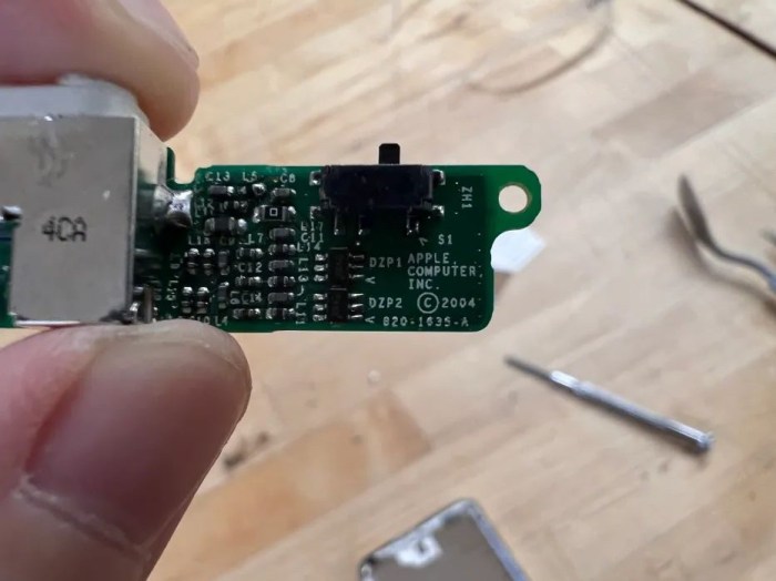
Headphone Jack and Hold Switch(820-1635-A)
Standard 3.5mm headphone jack. The material used for the headphone jack was typically metal, which provided durability and good electrical conductivity.
Hold Switch
Headphone Jack & Hold Switch Flex Cable(632-0260)
Flat Ribbon Cable: flat ribbon cable, which consists of multiple thin conductive wires sandwiched between layers of insulating material. The insulating material is made of a flexible plastic.
Connectors: At each end of the flex cable, there were connectors or plugs made of plastic or metal. These connectors allowed for the cable to be connected to the headphone jack and hold switch on one end and the main logic board on the other end.
Insulation: The cable also had insulating material to protect the conductive wires and prevent short circuits. This insulation was made of a flexible, durable plastic.
Hold button (plastic)
Plastic: Plastic is lightweight, durable, and can be molded into various shapes and sizes.
Hold button
White Plastic Dock Bezel
Rear case (stainless steel)
Hard drive cable
TUSHIBA hard drive MK2004GAL
Toshiba MK2004GAL 20GB UDMA/100 ATA-5 4200RPM 1.8″ Inch Mini Hard Drive Hybrid (HDD/SSD)
DMA/ATA-100 (Ultra)
Toshiba 20GB 1.8-inch Mini Hard Drive General Features: 20GB formatted capacity UDMA/100 transfer ratio.
ATA-5 interface 2 MB buffer 4200 RPM spindle speed 7.14 ms average latency 15 ms average seek time.
1.8-inch form factor Low-power consumption Power Specifications: DC 3.3V 500mA Regulatory Approvals.
Logic board
Logic board and display
Apple 820-1535-A Logic Board
Fiberglass or PCB Material: The main substrate or base of the logic board is usually made of a fiberglass-reinforced epoxy laminate material, commonly referred to as a Printed Circuit Board (PCB).
Copper Traces: Conductive traces on the PCB are typically made of copper.
Solder: Solder is used to attach electronic components to the PCB. It typically contains a mixture of metals, including tin and lead.
Silicon Chips: The logic board houses various silicon chips, including the CPU (Central Processing Unit), GPU (Graphics Processing Unit), memory chips, and other integrated circuits. These chips are made from silicon.
Connectors and Ports: Connectors and ports on the logic board may be made from various materials, including plastic and metal.
LCD Display (F-51824FNF-SLM-AD)
(Looks like there’s some screen fluid leaking)
Plastic Front Cover: touch-sensitive surface for user interaction.
Liquid Crystal Layer: The core of the LCD screen is the liquid crystal layer, which is made of organic molecules that can change their orientation in response to an electric current. This layer is responsible for controlling the passage of light through the screen and creating the images and colors you see.
Backlight: LCD screens require the liquid crystal layer. The backlight is typically made up of small LEDs (Light Emitting Diodes). Include semiconductors and various types of plastics or glass for housing and diffusion.
Thin-Film Transistors (TFTs): TFTs are used to control the individual pixels on the LCD screen. (semiconductor materials, such as silicon)
Color Filters: To produce full-color displays, color filters are used in LCD screens.
LCD Display back
White Front Faceplate
Covered the front of the device and housed the screen, Click Wheel for navigation, and other controls.
Battery(616-0198)
Lithium-Ion Cells: The core of the Li-ion battery is the lithium-ion cell.
Anode (Negative Electrode): The anode in a Li-ion battery is made of carbon or graphite materials.
Cathode (Positive Electrode): The cathode is made of a lithium-based material, such as lithium cobalt oxide (LiCoO2) or other variations.
Electrolyte: The electrolyte is a crucial component that allows lithium ions to move between the anode and cathode during charge and discharge.
Separator: A separator is used to keep the anode and cathode from coming into direct. The separator is a porous material, such as a polymer.
Protection Circuit: Many replacement Li-ion batteries, especially for consumer electronics like iPods, include a protection circuit board (PCB).
Connectors: The battery often includes connectors for easy installation and connection to the device.
Front panel
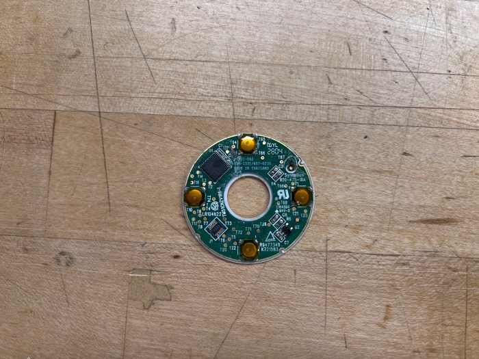
Click wheel(657-0230)
The click wheel operates by sensing user input through its touch-sensitive ring, which can execute multiple commands thanks to four mechanical buttons positioned beneath it.
The primary technology at play in the click wheel is capacitive sensing technology. When an electrical voltage is applied across two conductors situated closely but not in direct contact, it results in the storage of energy in the form of an electric field. Even after the voltage is removed, the stored charge remains, illustrating how capacitors gather and retain energy.
In the case of the click wheel, this property of capacitors is harnessed to detect the position of the user’s finger due to the capacitance between the human body and the conductive film beneath the plastic cover of the click wheel.
Flex Cable( Foxconn 2604)
Connect the click wheel and logic board
Design elements that interest:
Click Wheel: I appreciate the Click Wheel’s efficient scrolling and tactile feedback, which even includes a satisfying sound when pressed. It allows me to swiftly locate and choose what I want without the need for excessive button presses. When I try other music players for the first time, I often find that clicking their buttons can be uncomfortable and strain my fingers.
iPod switch button:The switch button is a feature I frequently utilize on all Apple devices, although it functions differently on iPods compared to iPhones or iPads. iPods are more prone to accidental touches, but the switch button effectively addresses this issue. It simplifies the process of locking the screen and the wheel. Whether I place it in my pocket or any other location, it doesn’t negatively impact my user experience.
Componts of the Printed Circuit Board (PCB): 1. 1 LCD Display screen 2. 1 Transciever AN29160AA (transmits and receives radio waves) 3. 1 Headphone jack 4. 1 DC jack 5. 1 Microphone 6. 1 Antenna 7. 3 larger Capacitors (temporarily stores electircal charge, used for filtering.) 8. Many mini capacitors 9. 3 large Oscillators (programmable timer or clock) 10. 1 mini oscillator 9. 1 Integrated Circuit / microchip 10. 1 Battery 11. 7 Switches (6 PCB printed buttons and 1 soldered-on button) 12. 1 large Potentiometer (variable resistor with 3 terminals) 13. Many mini diodes (control and redirect energy flow) 14. Many small transistors (amplify electrical enegry) 15. 5 Coil Inductors (temporarily magnetically stores electrical charge) 16. 2 mini inductors 17. 5 resistors (resist the flow of electricity to control energy) (I calculated the values using a color band calculator)
2 Unidentified PCB Components: 1. Serial# 270 2. Serial# CQ WM50HTP (I think it assists the transceiver in some way)
Other Components: 1. Plastic case made of 2 parts 2. 4 Rubber button cover parts 3. 3 screws 4. 2 Plastic covers for removable parts.
Tools used to take it apart: 1. Screwdriver 2. Solder sucker (to remove the LCD display screen) 3. Soldering iron 4. Wir cutters (to remove the protective plate)
Design elements that I like: 1. I like that the antenna is hidden inside the handle of the radio case. I used radios for my gallery technician job for years and I hated when the antenna would get caught on my clothes or on objects around me. I also hated when they dug into my side while heavy lifting or when bending in odd positions to install lights and artwork on the ceiling. 2. I like that it is voice-activated. This radio would have been really helpful with my job when I needed help with installation and my hands were full.
Making processes of a PCB: PCBs are mechanical supports that electrically connect electrical components using conductive pathways. 1. Create the circuit diagram 2. Create a schematic of this using PCB layout software. There are many open source options such as AutoDesk Wizard, KiCad and PCBWizard. 3. Design the physical board layout. This is what your schematic will be printed onto. The software used will help you compare them to determine the best board size. You will also need to decide how to design the connections for soldering. Through-hole components are the easiest to solder, but they take up more space than the more complex soldering options. 4. Etch your PCB. This can be done from home with a laser cutter, photo paper, a blank copper-coated plate, hydrogen peroxide (or ferric chloride with water) and a drill. -Laser cut the schematic onto the photo paper -Use heat from an iron to transfer it to the copper-coated plate -Put the plate into the hydrogen peroxide and shake it until the copper coating is etched off the unexposed copper -Sand off the printed ink. -Drill holes for the electrical components. Done!
Photos of behind the protective plate and behind the LCD screen display.